Frequency Interference

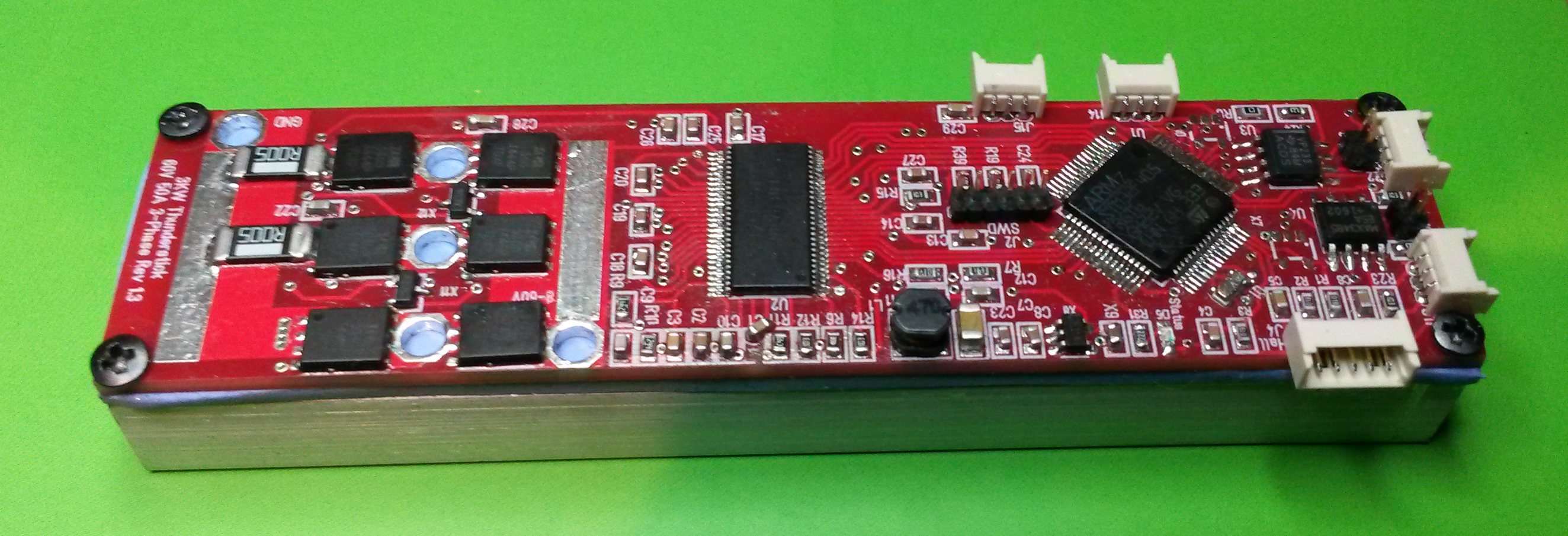
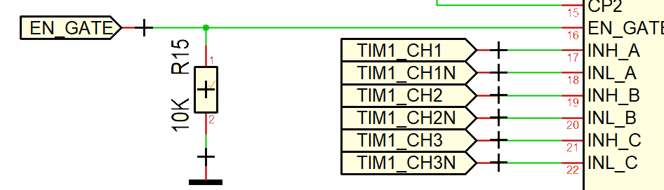
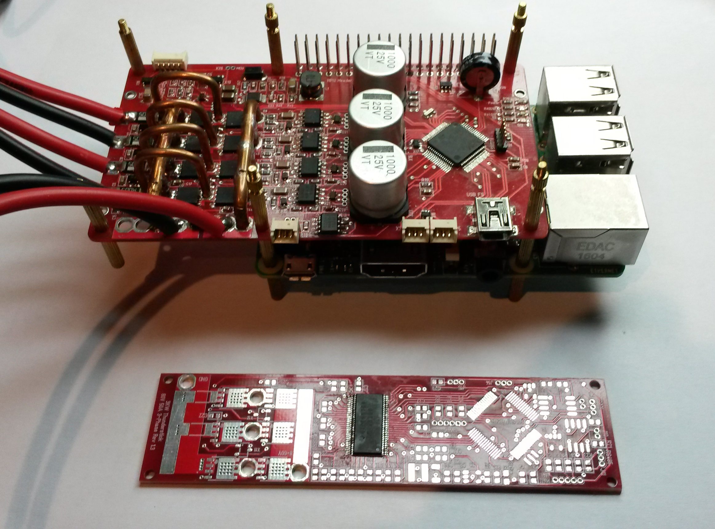
Testing Thunderstick I started to notice strange behavior as I increased MCU frequency – in fact I am unable to tick the MCU above 84Mhz powered from the DRV8301 Buck Converter. This indicate that I have interference between the Buck Converter and the MCU on higher frequencies. To prove my case I powered the board feeding it 5V directly and it suddenly works well on 168Mhz.

I have little experience with Buck Converters, but I assume I need to add a filter to separate frequencies. The challenge is that I have very little space to do so, so this will be a bit tricky to wire up and test. I could also try to change the value if the coil in the buck converter + I need to check datasheet for what frequency it uses.

It is also a bit tricky that I don’t have a Oscilloscope capable of seeing frequencies above 100Mhz, so I need to try to fix this blind. Adding a 10uH coil before the 3.3V regulator will probably do the trick, but it is a bit annoying as I should not need to do this – I might need to experiment with coils and capacitance on the Buck Converter to see if I can get rid of the high frequency ripple.

What is most likely happening here is that the Buck Converter generate high frequency ripple out as it generate my 5V power. If this is sufficient big and in the right frequency it will disturb the MCU as we try to achieve higher frequencies – well, for me to test and learn 🙂

Thunderstick working again

This MCU was hard to re-solder. You can see why by looking at the picture. I had a heck of a challenge with removing short-cuts and making sure every pin was soldered, but finally the Led blink normally and current usage is back to 10mA.

Another modification I need on some of the motor controllers are a EEPROM or FRAM to write data – I say might because I will only need that if I have a need to write things often. For now I can manage with a MCU Flash page for configuration parameters. The difference is that Flash can be written ca 100,000 times while FRAM can be written 10 trillion times. But, where should I put it ? Can you see any spare space on this board? I have to think about that one. But, for now I can start checking ADC readings – starting with DC-Rail.

Annoying misstake

What I have done here is to draw the circuit for DC-Rail and copied 2 resistor values without changing them – doh. I also assembled according to this and testet 30V, meaning I have injected 15V on a 3.3V ADC port – hmmm – wonder if that still works 🙁 To make things even worse – I actually have a not connected this to a TVS despite that I have one spare. That said – I also realize that some of these mistakes are unavoidable because as an engineer you reach a level where you have worked so long on a design that the only way forward is to test and find out what works what needs improvement. Maybe you could (as some do) spend far more time in design and avoid these errors, but my observation is that if you attempt that aproach you only end up using more time in design. My aproach is to forward a design to prototype as fast as I can to drive progress, but you have to find your own formula – whatever works for you. This one was annoying because I should have seen it as I assembled the components and I have wasted a day on an unstable MCU.

I fixed the resister, but the MCU is bust so I need to replace it.

I also discovered that removing even a resistor is close to impossible with the heat-sink on. So, at least the heat-sink work remarkably well. Mounting the heat-sink was required to test the mechanics, but I think I will continue without heat-sink and termal greace until we have a verified, working design.

Thunderstick Annotated

I have a strong preference for making some doc I call “Annotated Schematics” as I start coding and making a project. This doc break up and explain the schematics, programming info etc and everything I basically need as a SW developer to get going. The annotation above is the 3D model annotated to show content and position on the PCB.

  1. RS485
  2. RS485 terimator
  3. CAN
  4. CAN Terminator
  5. MCU STM32F405RG
  6. IO Connector
  7. IO Connector
  8. SWD old 6 pin format.
  9. Power lane for 60V+. Designed to solder on a 3mm wire if needed.
  10. MOSFET array. 3 x Half H-Bridge as classic for 3-phase design.
  11. Ground power connector
  12. 2 x Shunts to measure currents.
  13. Drill holes to mount heat-sink.
  14. Power lane for ground to cMOSFET’s.
  15. 2 x Temperature sensors.
  16. Power connector for 60V+
  17. DRV8301 Gate Driver, Buck converter and Motor logic.
  18. PSU components. 5V from DRV8301 and 3.3V from SPX3819.
  19. Ceramic crystal 8Mhz.
  20. Hall sensor/IO connector.

Testing on Thurderstick have gone remarkable well. Downloaded code yesterday and will start spinning 1KW motors today on 30V. I only have 30V/10A PSU for the time being and that should be more than sufficient for now as focus will be on the getting sensors and motor algorithm working.

Assembled Thunderstick

The wires and caps are a bit tricky to get right. the cap should actually be the other way, but I need access to the SWD so had to bend it over the MOSFET’s. This mounting is not ideal, but it is working. It is a 2000uF 63V Electrolyte that is mounted. The only thing I actually miss now is a TVS to support the capacitor, but this will have to do since we only will play with 12/24V anyway. I have not mounted the 3mm power wires on the board for now, but the rest is mounted. The first objective to evaluate the mechanical solution have gone well – I would like to consider a few options, but I am quite happy so far. The idea is that this motor driver is more or less an extension of the wire/structur holding the actual motor.

Mounting the heat-sink got a bit greecy since I added termal greace this time. It just have to dry up and I can use a knife to cut of edges and we can get going.


Thunderstick 3-Phase Testing

Finally mounted one unit, only lack capacitors and power wires and we can start spinning motors. I assembled 5mOhm shunts for now to experiment + I used 30V/100A MOSFET’s since I have few of the 60V and this should not be using 60V on this anyway. I will limit testing to 12V and 24V which is sufficient for now. Mounting the heat-sink was straight forward, so I am really pleased with this design so far. I need to be a bit creative as I mount the power cables and add the main capacitors.

Since this is a motor controller I would usually power on without MOSFET’s (I actually have), but the schematics above show a very important detail – DRV8301 have a separate enable for the Gate Driver that is pulled to ground, so the driver bit will start in off position. Also – the driver have short-cut protection so we should be on safe ground to experiment. These details are very important on these types of design because otherwise you risk switching it on just to watch your MOSFET’s burn up – been there, done that!

I also like to point out that the reason I made this stick was to provide a low cost quality ESC for heavier drones. This got components on one side, easy to mount heat-sink etc so I will be excited to see what I can achieve in terms of power – for now my target is 24V@20A – which is 480W.

MC3P60V50A Thunderstick Testing

I started assembling Thunderstick and also start finding things I need to change. Mostly small things except one schematic error on the buck converter. It is not fully assembled yet, but 3.3V is working and it’s time to run the MCU.

  1. The mechanical mount holes are to close to ground, meaning the bolts my connect to ground by mistake.
  2. I have 2 capacitors on 60V input and have used standard 0603 components. I tested them at 30V yesterday, but I need to replace them capacitors that can handle 60V.
  3. I have no power led. This was done to save space, but I seriously want a power led on 3.3V.
  4. This is a bit worse as I had a schematic error on the buck converter resulting in 5V being 50% of input voltage. I fixed that, but I also had to adjust R12 a bit to get 4.2V out. Mounting the SPC3819 I now have a nice 3.3V. I had some trouble with the buck converter before I realized that R12 was not properly soldered.
  5. I want the new 2×5 pin SWD on the board. This uses a 6 pin and the idea was to use a JST connector, but the added wiring made SWD sensitive. Using a single 5 or 6 pin is less attractive than 2×5 pin since they are stable to mount on and come in bulk.
  6. BOM list needs to be optimized, consistent numbers and E values.
  7. J15 are to close to the edge.
  8. J14 are to close to the edge.
  9. J16 overlap resistor
  10. J11 overlap resistor
  11. J4 are to close to the edge

I have to admit that this project looks far cooler than I expected, but I still have to mount the MOSFET and do a lot of proof of concept testing. It will be very interesting to read temperatures and currents etc.

3KW 3-Phase Getting Assembled


My Thunderstick PCB’s arrived some time ago, but it has been very hectic at work so I simply had no time to work on it. I also have a new 1kw motor that will be nice to test. The pictures above is the board with DRV8301 mounted. I have to start with this because I need the PSU from this to drive the MCU. This is a 8V to 60V driver, so it should work well at 12V,24V and 48V with a design target of 50A out.

I almost ditched this board due to the more powerfully version in the back of this picture that serves 4 channels and have a Raspberry PI mounted, but looking at how small and neat the Thunderstick have become I admit that it is much nicer to use on drones with 3-phase motors. As mentioned before the larger board lacks motors to put it to justice as we speak. Also counting components the smaller have ca 60 while the larger have ca 160 components. I was actually tired after mounting the larger one.

This shows the backside of the board with pads for MOSFET and DRV8301.

This shows the thermal 2mm rubber isolation and the heat-sink mounted. The idea is that we cool down the PCB and pads and as such cool down MOSFET and DRV8301. The design is expected to operate without heat-sink, but then it is the issue about theory and practice. It will be interesting to learn. I have not been able to do that on the larger board yet because I did a mistake not letting the MOSFET pads through so the MOSFET’s are on their own. I can test logic, but not power like that. On this I actually got 20 PCB’s so I will be burning some of them to do research on power lanes later.

This last picture show the new 1KW drone motor I plan to use. The last motor was more powerfully, but it required a bit of mechanical mounting to use it. This can just stand on the table thought I will need some mounting as I start running in speed. 48V * 20A is 960W and I have a 50V 0-20A PSU (that I need to assemble) so I can actually support this test.

Ethernet/Wifi Hat Height

This is the Ethernet board 3D from front. This 3D model is a bit ruff, but it serves its purpose and looking at this I realize that the RJ45 connector is to high. This is not critical as I can adjust hight by extending the pins to the next board (not shown) and use extended PCB spacers. But, I could also solve this by using a different RJ45 that is lower and positioned half way through the PCB. I could also just use magnets and remove the RJ45 itself which is common in some industrial solutions, but I prefer using a standard RJ45. The funny thing is that I was concerned about the antenna connector which also is on the edge – which means I have the same challenge with NB-IoT, LoRa and GPS antenna connectors.

The current board (rev 1.2) uses LAN8710 and looking at the chips I have decided to move to LAN8720 which is smaller, but looks easier to solder. But, I will order the LAN8710 board anyway since I have a few chips around.

I currently experiment with a Olimex board that use LAN8710 and the code is actually for LAN8720, so the chips are compatible. LAN8720 is a simplification of LAN8710. It will be interesting to know if I can manage soldering these QFN packages for hand because I have a few chips that I have avoided due to this.

The Olimex board (shown above) works OK and add Ethernet and SD-Card + a few pins. Coding this rather straight forward, but I am a bit puzled as to why they don’t provide proper sample code. It is actually not much sample code demonstrating Ethernet – that said it is basically only the init that is different from Wifi. I use Arduino libs at present, but will switch to the full SDK later.

ESP32 Ethernet Hat Challenges

I am a bit stunned by the memory usage on ESP32. This is a 178 line test script that uses wired Ethernet and it only send an UDP message out – the program uses 645606 bytes – which is 49% of available space. Luckily it does not increase that much, so I assume this is the core libraries. I would also like to understand why a 4Mb Flash is reduced to 1310720 bytes… The answers are probably online somewhere.

A more annoying issue with ESP32 is it’s SPI support. I wrote sometimes earlier that I lack info about SPI, but I finally found some doc that states it can support up to 80Mhz on selected pins, and 40Mhz if you select your own pins – but only in Master mode and only in Full Duplex. In Half Duplex and Slave it might be reduced to something like 8Mhz due to lack of DMA support etc – bummer. This is not a showstopper, but it will force me to use reduced speed on SPI with ESP32 modules in the stack – which is a bit annoying since this is an Wifi/Ethernet adapter.

Coding on an Olimex GW board works fine – I am not able to test SPI here, so I will use a different board for that, but Ethernet works just fine so far. I must admit that ESP32 is a good match for Arduino libraries. The libraries are not as flexible as the full SDK, but it requires very few lines to get something up working. The main limitation that the libs are blocking can also be overcome by putting both CPU’s to usage.