This just a mock-up of an actual module assembled from 7 IO modules using the later design. Size is just illustrative as I play around with ideas. I am waiting on project boxes and will adjust everuthing to that.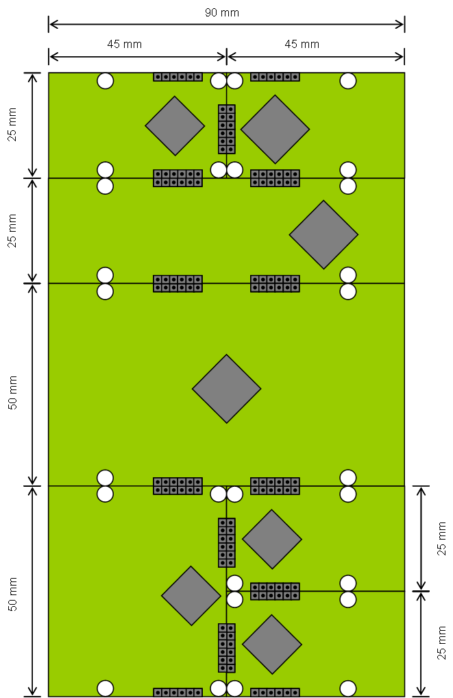
So far I have only draftet connectors as 5P headers. I am thinking about doing CAN only and maybe let each board have one connector that plug into a adapter board at bottom that fit into the project box. This would be a PCB only to create a backbone bus with Power and CAN-FD. The entire PLC will be flat, low profile. Using this system we can deliver modules that is 45 or 90mm wide and 25,50, 75, 100 aso in Height. CAN-FD interconnect within a box and from box to box.
It is possible, but I need to think about the mechanical solution here. An Alternative to having a Bus-board at button is to create a cable-PCB and soldier a specialized interconnect cable for each box. The advantage is lower profile, the disadvantage is more manual work. Cost wise it is more elegant to just plug things together.