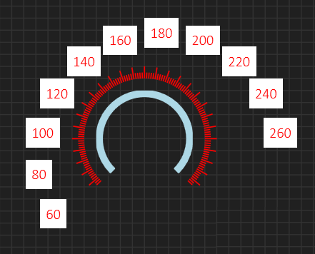
Labels are equally easy – just use the same center and compute cartesian coordinates for the positions you want labels on. But, as you can see from the example below I get an additional issue. I used the coordinates as the upper, left corner and labels at left comes closer than labels at right etc. I have displayed the background white to illustrate the issue. To solve this you need to calculate the width of the text labels and adjust the label so the coordinates are on center. That way the labels will adjust so they look to be at the same distance. Also notice that while I have Major ticks at every 10 degree, I only display labels at every 20 degree by choice. Even label at 20 degrees is a bit tight, but this is just to illustrate that they are different. I will also add another label control that display only selected values as a separate control.
So lets calculate with and height and adjust to center…
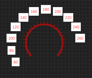
This one surpriced me, but notice that the white background area is quite large – this is Padding set to 5 and the calculation don’t adjust for that.
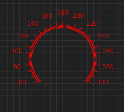
Adjusting for padding and moving the labels a bit closer + adding the correct endvalue we get a perfect result. Label “300” will be a little closer than label “”60” simply because it is wider, but I decided not to compensate for that for now.
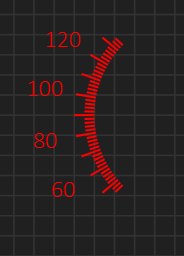
This last screenshot is just to show the obvious – I have created circular components that have a start- and end- angle in degrees, so you can create whatever gauge you want. Even more important is that you can decide what component(s) to change as the value change. Usually we change the needle, but I can just as easily change the ticks and labels to rotate with a fixed needle. We are now getting into the many effects you can create and the reasons why I want the user to be able to create theire own custom gauges using a pick & mix. I will add in some standard gauges, but I think the concept that you can make your own is far more important.