Sadly the headers occupy ca 10mm of 25mm, so to get Ethernet RJ45 fixed I needed 35mm width on the modules. The MCU module will be fine, but having two IO modules will require more space. 10mm extra is not the end of the world, but the design draft is also 4 PCB’s per module, so I wonder if I could get cost and size down by making modules with MCU on as follows:
The issue is that getting rid of the headers and reducing from four to two boards are fine, but with the target height of 25mm I still use up to much on the mounting holes.. M2 Mounting holes with 1 mm clearing is 4 mm. I also only gain 5 mm on width while I suddenly have to find space for the MCU. I can use a smaller 48 pin MCU rather than a 64 pin, but the saved space is scarse.
The disadvantage of doing this is that 25mm height will only serve the smallest modules. Another disadvantage is that we add a MCU on each module doubling MCU cost. And I don’t realy have a solution to interconnect boards here yet.
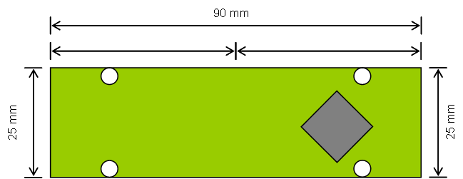
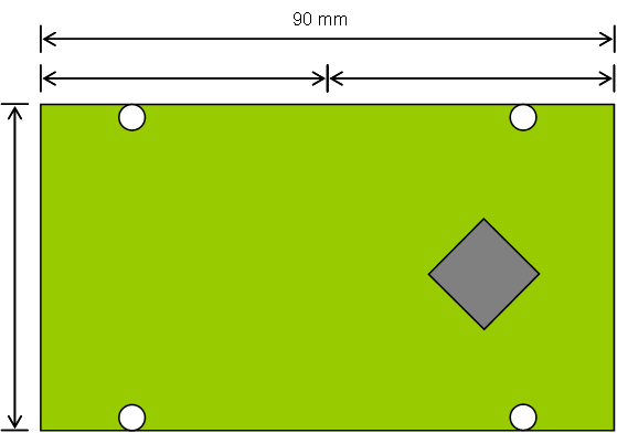
The advantage is that we reduce from 4 PCB’s down to 2. Interconnecting two modules are done elegantly on back to back using a UART TTL since you will automatically cross Rx/Tx. Another advantage is that we in case of space starvation simly can customize the module by (1) using 50mm Height or the full 90mm Width. Below are illustrations showing 90 x 25mm and 50x90mm.
I was thinking of using a TTL Uart between two modules mounted back to back, while I still use CAN for modules in general. Using a TTL UART is free – no space except for a back to back connecter. But, CAN-FD is also extremely small size with SO23 package Tranceiver so I could use CAN-FD on everything. All IO between MCU and IO is now custom. To faciliate Ethernet and Wifi I could sacrifice one mounting hole, but with scalability in Height/Width I am not stuck to the minimum size.
As mentioned before 90mm is selected because we can use standard PLC Boxes where you can have connectors on both sides.
—
A word about KiCad and why I do the mock-up in PowerPoint: I just upgraded to KiCad 6.08 and it’s been a while since I used KiCad so I need to re-learn the PCB tricks. KiCad is great then you know it and use it often. I will return later with more accurate mock-up’s on the mechanical design.