86 components on 25 x 45 mm – it don’t look like much in 3D, but it was actually quite hard to route even on 4 layers.
- MCU STM32G491RE
- DRV8313 for 3 x PWM
- 4 x Current Sensors
- 1 x DC Input Sensor
- 1 x CAN-FD Tranceiver (IPC)
- 1 x RS485 Tranceiver (IPC)
- 32Kb FRAM
- SW controlled terminators
- 8 – 24V support
- 300uF capacitance on 24V on-board.
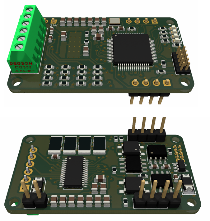
Some of you will recall that I made a similar module before (below). This was 20 x 50mm and 2 layers. It has a 60V DC/DC that worked with a tweak and hall sensors that I never tested – but it was components on one side only. The motor driver worked well – it was CAN here as well. I never used F303, I just used F103 instead. But, it is a 48 pin version of the MCU, No FRAM and no current sensors on this – and it lack capacitanse on-board. This old board was tested with 50ich Volt, but I realized later that some of the capacitors did not hold the speck – fake Chinese crap. The new board will not be using components bought on AliExpress – lesson learned!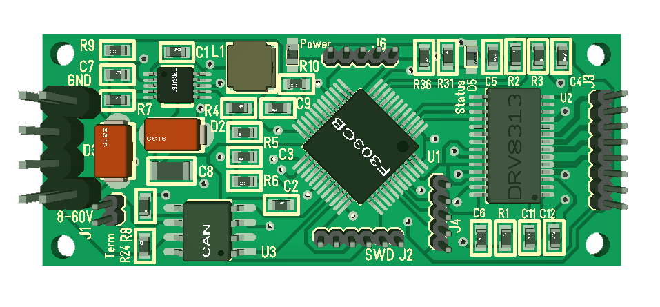
Having done an Ethernet Module and a PWM module I want to just get those assembled and evaluate the format as I go. Looking at the module above you can see that is no space for 2 extra SOP8 circuits and 4 current shuts – the circuit above is 40 components, while the new one is 86 components – I literally have no free space on the new one.