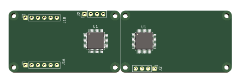
The two first modules I will create is Ethernet and Serial (RS485 & RS232). I have several paths forward to create this, but the most obvious is to create two modules that can go back to back. To connect these two I use a small PCB connecting CAN on J2 – the four pins are 3.3V Power (or 5V ?) and the two CAN pins. The bus board can hold the PSU and lanes to interconnect CAN between boards. J2 is on the top at left side and bottom at right side.
Another option is to use the space under the Ethernet Module (or back side) to have a serial out through a low profile mini-connector directly on the Ethernet module. This will make a very small all-in one PCB. Yet another option is to use an UART TTL back to back. The UART is nice for debugging, but could also connect directly between two boards with a jumper. I need to actually make these boards to see how much space I have.
The advantage with the Bus board is that I can put PSU here – the alternative is to put PSU on each board – which can be assembled on the back.
The main drawback right now is that I only have LQFP64 MCU’s in stock – I managed to buy some a bit earlier, but getting hold of any STM32 these days is difficult. That also goes for semiconductors in general andit seems as we will see 2024 before this get easier 🙂