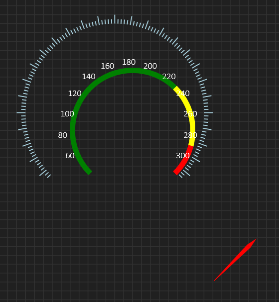
One of the challenges I have is that it is a big difference from making a library component and making a BSA supported component. Take Width/Hight/Center/Radius of a circular gauge as an example – this is straight forward in your own code, but doing the same on a visual designer is challenging because the visual designer snap to grids and it can be difficult/impossible to align circular components with diferent radius correctly. The example above is a bit made up, but it illustrate the problem and this is a designer only problem.
The easy solution is to implement a “UseParameters” property forcing the controls to use fixed property values for a reference design. This works – the difference is that you then use a common fixed coordinate reference and ignore size markers in the designer. Dealing with circular designs I find this to be a must.
To make this scalable I need to track design width/height and compute the difference to actual width/height as we draw the components. It is important that we scale by drawing with re-computed coordinates and don’t attempt a zoom that will give a similar, but fuzzy result.
To make it easy to align coordinates I also show reference coordinates for parameterized designs. This challenge was very obvious with circular components that needs to fit together, but I also wonder if I should implement this all over – parameterized design that can override the visual click&drag designer? To switch off the grid will only make things worse as it becomes very difficult to align anything. I already have two grid sizes to assist on this, but parameterized design seems as a savior for those situations where we will struggle with the grid.