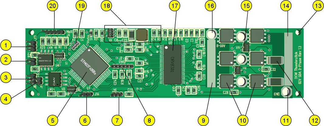
I have a strong preference for making some doc I call “Annotated Schematics” as I start coding and making a project. This doc break up and explain the schematics, programming info etc and everything I basically need as a SW developer to get going. The annotation above is the 3D model annotated to show content and position on the PCB.
- RS485
- RS485 terimator
- CAN
- CAN Terminator
- MCU STM32F405RG
- IO Connector
- IO Connector
- SWD old 6 pin format.
- Power lane for 60V+. Designed to solder on a 3mm wire if needed.
- MOSFET array. 3 x Half H-Bridge as classic for 3-phase design.
- Ground power connector
- 2 x Shunts to measure currents.
- Drill holes to mount heat-sink.
- Power lane for ground to cMOSFET’s.
- 2 x Temperature sensors.
- Power connector for 60V+
- DRV8301 Gate Driver, Buck converter and Motor logic.
- PSU components. 5V from DRV8301 and 3.3V from SPX3819.
- Ceramic crystal 8Mhz.
- Hall sensor/IO connector.
Testing on Thurderstick have gone remarkable well. Downloaded code yesterday and will start spinning 1KW motors today on 30V. I only have 30V/10A PSU for the time being and that should be more than sufficient for now as focus will be on the getting sensors and motor algorithm working.