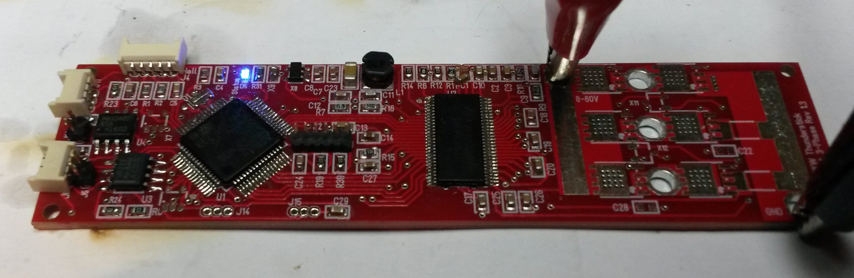
I started assembling Thunderstick and also start finding things I need to change. Mostly small things except one schematic error on the buck converter. It is not fully assembled yet, but 3.3V is working and it’s time to run the MCU.
- The mechanical mount holes are to close to ground, meaning the bolts my connect to ground by mistake.
- I have 2 capacitors on 60V input and have used standard 0603 components. I tested them at 30V yesterday, but I need to replace them capacitors that can handle 60V.
- I have no power led. This was done to save space, but I seriously want a power led on 3.3V.
- This is a bit worse as I had a schematic error on the buck converter resulting in 5V being 50% of input voltage. I fixed that, but I also had to adjust R12 a bit to get 4.2V out. Mounting the SPC3819 I now have a nice 3.3V. I had some trouble with the buck converter before I realized that R12 was not properly soldered.
- I want the new 2×5 pin SWD on the board. This uses a 6 pin and the idea was to use a JST connector, but the added wiring made SWD sensitive. Using a single 5 or 6 pin is less attractive than 2×5 pin since they are stable to mount on and come in bulk.
- BOM list needs to be optimized, consistent numbers and E values.
- J15 are to close to the edge.
- J14 are to close to the edge.
- J16 overlap resistor
- J11 overlap resistor
- J4 are to close to the edge
I have to admit that this project looks far cooler than I expected, but I still have to mount the MOSFET and do a lot of proof of concept testing. It will be very interesting to read temperatures and currents etc.