16xServo Hat

This is rev 1.3 of 32xIO/Servo Hat. It’s been a few revisions that I never bothered to build because the original is working well. But, I need some changes on this:

  • SWD need to change to new format.
  • Connection to SPI1 need resistors.
  • 2nd Power connector needs to be added.
  • Connection between motor and 5V USB can be moved into board.
  • Leds can be moved into board.
  • Adding protection diodes on wrong polarity.

The main change I want is however new Servo/IO connectors. The right-angle headers used here are great, but they have no mechanical fittings and are candidates for falling off during vibration. How I can achieve this is a puzle. I might have to use JST Micro 3-pin in which case I can achieve 16 IO/Servo ports maximum. I am however thinking that is OK because firstly I can stack board, secondly 16 x IO is a lot + it is much easier to ensure 16 x PWM timers and use hardware for higher pulse accuracy on Servoes.

That said I think the 16x IO/Servo Hat can start at revision 1.0 and we upgrade this to rev 1.4, meaning I maintain both for now. The 32xIO/Servo Hat is after all a cool hobbyist board + it is the closest I have to a generic GPIO Board.

ESP32 based Ethernet/Wifi Adaptor


RC1 of the ESP32 based Ethernet/Wifi Hat can be seen above. The module follow the same standards as the STM32 based modules with SPI backbone CAN and USB. The board can fit straight on a Raspberry PI or be combined with any module described in this series. New to this version is that I removed the IO ports of the previous version and added a wired Ethernet option using LAN8710 Transceiver. This is a 10/100Mbs Ethernet and the lwIP stack is already on the ESP32 module. In Effect this gives Wifi, Bluetooth and Ethernet Acces in addition to CAN, SPI and USB. 

ESP32 have a build in antenna that we still can use, but I added a 2.4Ghz antenna option that can connect to IPEX antenna on some modules. This allows us to use at least 3 different ESP32 modules available on the marked. The 3D model below show the module annotated.

  1. CAN Connector. The actual connector is a right angle 3-point micro connector. Basically the same as used on all boards.
  2. Terminator for CAN. If connected add 120Ohm terminator resistor.
  3. LAN8710
  4. RJ45 Ethernet with magnets.
  5. Ethernet power led. This indicate if Ethernet is powered on or not. I use a separate SPX3819 that is controlled by ESP32 enabling me to switch off Ethernet if I want to.
  6. 2.4Ghz antenna connector for Wifi/Bluetooth.
  7. USB Mini connector. Needed for programming the module.
  8. Leds
  9. CH340G UART to USB. I have used these for a while and I am very happy with their performance.
  10. External 5V power connector.
  11. Internal PSU regulator
  12. ESP32 module.
  13. Reset connector.
  14. Leds
  15. Raspberry PI connector using 5V and SPI.
  16. Boot connector
  17. CAN Transceiver.

Ethernet Ground Plane

Just showing the ground plane on the Ethernet/Wifi Hat. I am very pleased with this one and the approach I used here. Earlier as I routed I have routed on both sides with ground plane becoming very fragmented. On this one I only used ground plane as an exception and only for minimum distances. The cost is that I go forth an back a little, but the result was a much better ground plane with no fragmentation of areas.

I feared routing Ethernet would be difficult an result in a very fragmented board, but it has actually gone much smoother than expected and with a very good ground plane as result.

I do however keep promissing myself to move to 4 or 6 layer PCB’s once I have the prototypes working. I don’t need extra layers for routing, I need extra layers for EMC and noise reductions as I start penetrating higher frequency signals. But, well – if this works on 10Mbps and not on 100Mbps we know the reason and how to fix it. I will annotate the new Hat later.

Modular Control System

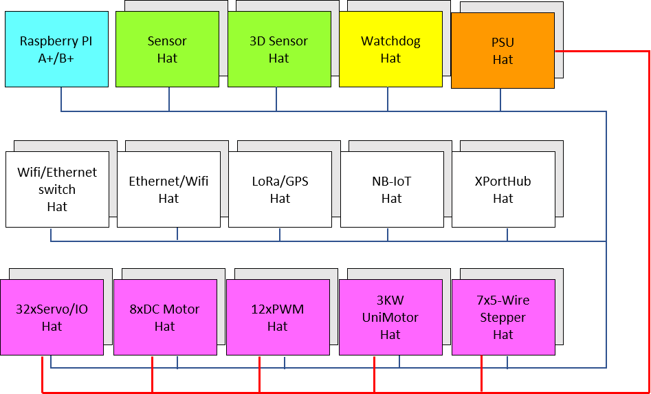
This drawing is an overview of the Hat’s in progress. A few is only on the planning stage, but most electronics is on prototype level and SW is coming on.

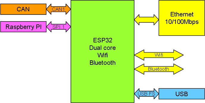
Raspberry PI is the obvious core if I need heavier processing. Due to the nature of it’s SPI I can only connect one of these on the same bus. But, it is not given that the bus here must be SPI as we also can dig into Ethernet, Wifi, Serials, CAN, LoRa and NB-IoT.

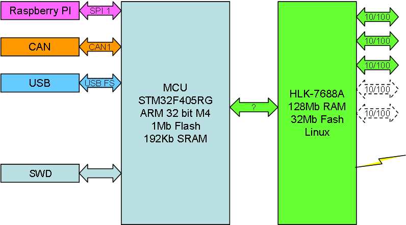
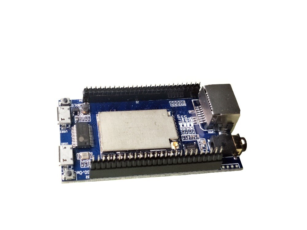
Wifi/Ethernet Switch is new. I am thinking of HLK-7688, but I need a switch regardless to use Ethernet and Wifi in a system. I will do some experiments this authumn to see if I can achieve something here.

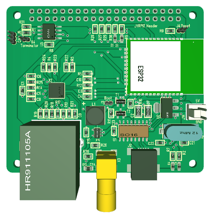
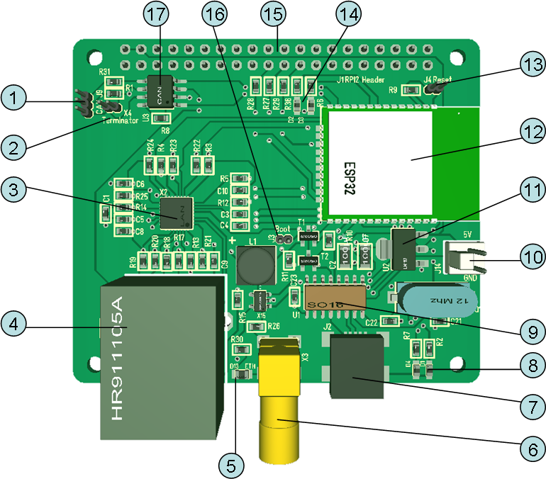
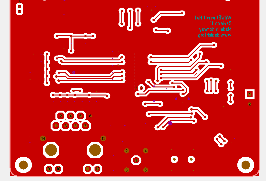
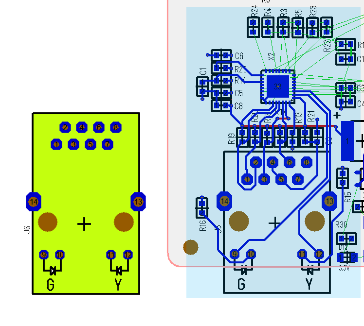
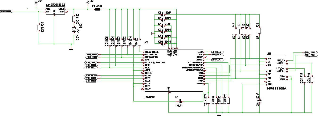
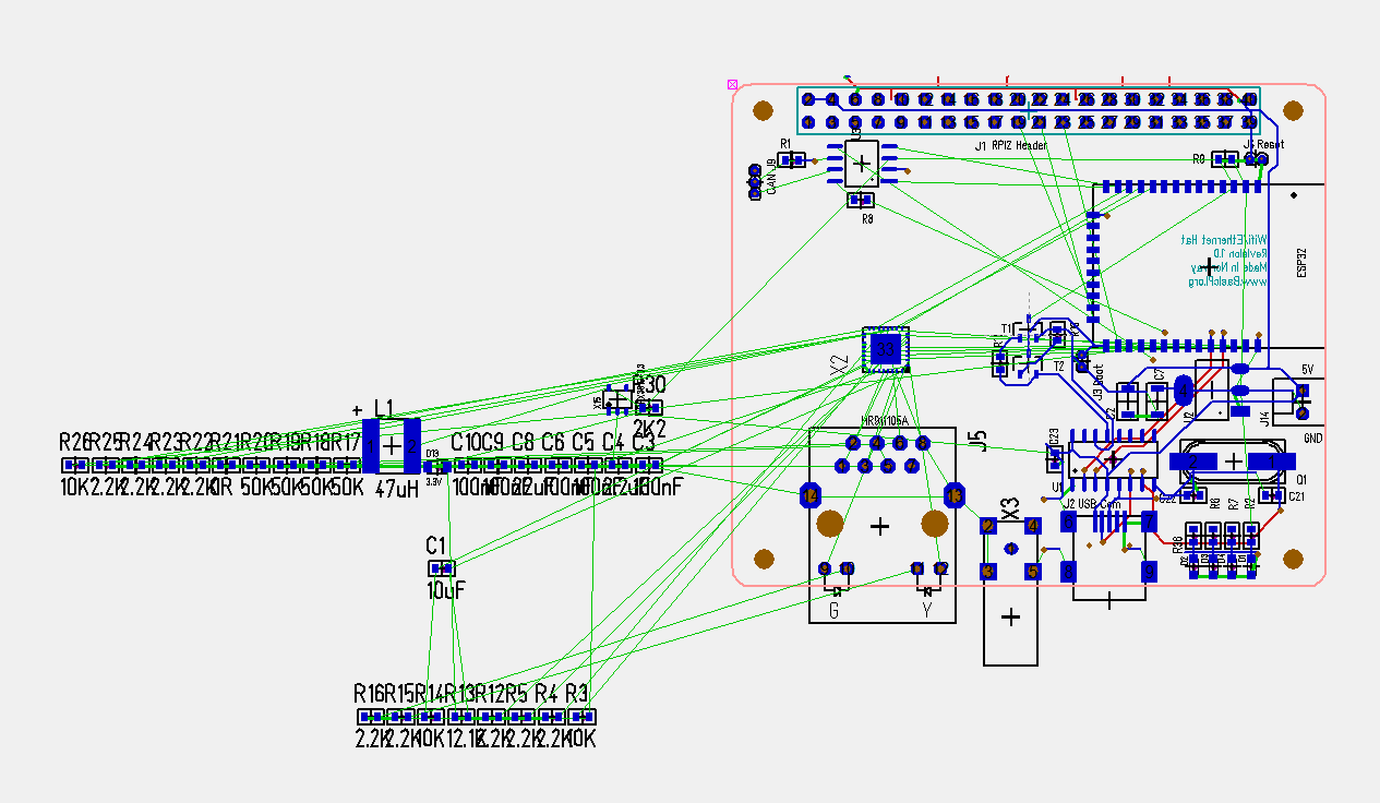
Ethernet/Wifi Hat is on it’s way. This is a simple replacement of Raspberry PI that allows me to add multiple Ethernet/Wifi connection points. Excellent for secondary connections or low cost adaptors. Or well – low cost – the price of a Raspberry PI is hard to beat due to it’s high volume production, so lets see.

LoRa/GPS is on it’s way. I have the first PCB (with errors), but I have not found the time to assemble them yet. I actually considering updating the PCB before I crack on. I am a bit eager to learn more about this technology as it provides free radio up to 12ich km in line of sight.

NB-IoT Hat has same status as LoRa – I have the PCB, but lack subscription and time. I actually need a SIM card w/subscription to connect to the telecom network for this – again a technology I would like to learn more about. If my understanding here is correct I can connect from isolated places to monitor data with this.

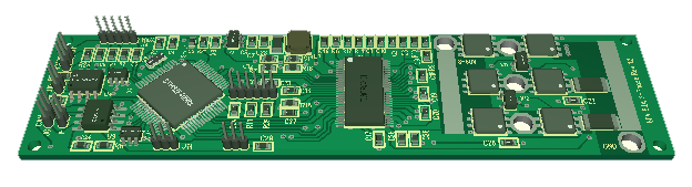
XPortHub is made, but I need a revision + I also consider making a variant with Pro-EP10 or similar to get a Ethernet connector. The SW on this is also coming on as this is the project I use to build infrastructure. The plan is to duplicate AL/tools on all Hat’s and start adaptions later this year.

Sensor Hat is on it’s way. This is a Hat offering connections to multiple sensors Analogue, Digital, SPI and I2C.

3D sensor is only on draft level. I have components and need to find time to experiment. This will include GPS, Magnetometer, Gyroscope, Accelerometer, Pressure (Altitude), Temperature and humidity. The target is 3D sensors for motion drones.

Watchdog is new on this list. The idea is a separate Hat that monitor/power on/off the rest.

PSU is 5V PSU feed from higher voltage + maybe I make the watchdog capacity here. Watchdog and PSU are ideas, but not very mature ones – that said it is obvious that I need to find a battery/PSU solution for my systems.

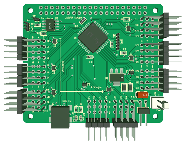
32xServo/IO Hat – I have an older version of this, but have not ordered the new PCB. I need to do a review with focus on the Servo part with some testing. Some pins can be driven by timers, but I do not have 32 PWM channels, meaning that some pins will need software feeding or be IO only. It might be that this is reduced to 16xServo +16xIO etc. To be honest 16 servo ports are rather high density + I can stack these boards up. I also have an issue with these right angle header connectors so it could be an idea with proper connectors that do not fall off etc – I have to look into options.

8xDC + 16xIO Hat is not ordered. Again I have old versions that I want to experiment with first. This Hat might actually be ditched because the 12xPWM can drive 6xDC + I have a ESP32 project that also can drive multiple DC motors if I need more optional space.

12xPWM Hat is on it’s way now. This is maybe the most powerfully motor Hat I have as it can drive 12xSolenoids, 12xPWM signals, 6xDC Motors, 4×3-phase motors or 3xSteppers with current sensors.

3KW Universal Motor Hat. My 160 component steam-punk monster. My wife named this Steam-Punk Driver due to the thick cobber wires. I have to admit that I have assembled, switched on PSU power that works fine and hidden it for a boring day The driver is so powerfully that I lack a project/usage for it. But, the 3KW Thunderstick targeting 3-Phase motors is on it’s way + I am waiting for a new motor. I actually have a 3KW motor, but I need mounting for it + hrmfff PSU to test. The 3KW UniMotor will be completed because I like that project, but I fear I lack project for it.

7x5Wire Stepper is assembled and tested. Motor code is ready, but it needs a new PCB with minor fixes and AL infrastructure so it can go into a system. This is dedicated the small 5-wire steppers that cost ca 1.- USD.

LAN8710 vs Pro-EP10

Again I am not done routing, but I wanted to illustrate ca the space cost of adding an Ethernet Phy and why I was so interested in Pro-EP10. You can see Pro-EP10 footprint at left in green, while LAN8710 and RJ45 w/magnets build in is in blue at left. Using Pro-EP10 would be a huge space saving + the Linux means you can have things like Web servers on separate processors – which we also can since we have ESP32 for this purpose.

The drawbacks with Pro-EP10 is cost (ca 18.- USD), reduced bandwidth through a serial Interface and more complicated toolchain on an embedded Linux. The later is not really that limiting because the MCU’s we use will struggle with higher bandwidth, so it will work out. I already have a Pro-E10 and it will cost me a bit of time and ca 20.- USD to do a demo Hat, so lets see. I am actually considering adding Pro-EP10 to XPortHub.

That said HLK-7688 is much better beacause it offers Wifi and 5 Ethernet ports with a 150Mbps bandwidth switch build in – assuming I can use the SPI as I want and get control over the toolchain. The later is the main drawback with these Linux options. ESP32 on the other hand is well supported and have an excellent, easy to use Toolchain.

Wifi/Ethernet Hat

Not routed the Hat yet, but got all components on the PCB and it looks possible. Using an optional 2.4Ghz antenna on this one. It will take ca 1 week and I probably have the first draft routed. It tends to og fast once I start. What I usually do is to do a bit now and then and suddenly it’s done. I have mentioned this before that I find PCB Routing like a relaxing mind-game.

Wifi/Ethernet Hat Drafts

Getting on with my ESP32 based Wifi/Ethernet Hat. First draft of schematics below. This is the first time I try LAN8710 so all bets off. I am most worried about the 100Mhz signals here. The next picture show components before I place and route the PCB. This looks tight tbh.

LANEnable will switch power on/off enabling me to run with only Wifi or only Ethernet. The rest is IO for Ethernet RMII Interface. I have ordered some breadboards to Experiment With this before I see any point ordering it.

Ethernet Hat’s ESP32/HLK-7688A

I decided that I want to make 2 different Ethernet/Wifi modules With different purpose. With Raspberry PI it will be 3, but RPI and ESP32 overlap in functionality.

ESP32 with Ethernet/Wifi/Bluetooth is a very attractive “Connector” solution where I can add more connections by adding multiple Hat’s. I can sadly only add a single Raspberry PI since it only support Half Duplex Master on the SPI. 

HLK-7688A is attractive because it is a switch/router. I can probably do this with Raspberry PI as well, but with HLK-7688A it was straight forward to connect with the OpenWRT package. I am not so sure with interconnection to the backbone, but that is work to do. I have to admit that I am still a bit undecided on HLK-7688A because support and information is not that great, but we will see. And even if Raspberry PI can be used as a Switch/Router it still have to deal With the Ethernet/Wifi IO bandwidth. It maked perfectly sense to offload this to a HLK7688A based module.

The main attraction with HLK-7688A is the switch/router capability. If I connect using Ethernet or Wifi I will need that regardless and having it as part of a control module is very attractive.

HLK-7688A Suit Prolific driver not working

I recently purchased an small dev kit for HLK-7688A (above) and noticed that it has a Prolific USB-to-Serial port. Connecting it I get this message:

Windows detects the port, but the driver will not open it. I assume this is a fake chip issue again. I have had this issue with Prolific before – which is why I try to avoid devices with Prolific on. I will see how I can get around this.

I respect that fake chips are a problem, but it is not my problem! My respond on things like this is that I add Prolific to the list of companies I avoid. 

In this case I might need to grab the UART TTL signals and use a CH340 circuit so I can use the dev kit if I can’t get the Prolific junk driver to work. I will also ask the vendor to ditch Prolific and use CH340 to avoid the problem. In this case I might very well have picked up a copy as this is an open dev kit.

3KW Thunder Stick

This is my 3KW 3-Phase Motor Driver Rev 1.3. Revision 1.0 and 1.1 had air wiring, 3 current sensors and output at right. Rev 1.2 lacked RS485 while Revision 1.3 have CAN and RS485 + 2 temp sensors between MOSFET’s + I solder on cobber wires directly on PCB for 60V and GND to sustain 50-100A. The actual rating for the MOSFET is 160A per MOSFET, but my math indicate we can sustain 50A continuous due to PCB and Heat dissipation.

The VESC (Vedder design) uses more powerfully MOSFET’s, but is also limited to 50A continuous due to heat dissipation. My design allow for a heat-sink on the back. My math indicate that I reach ca 1W dissipation at 35A per MOSFET, so I should be able to sustain 35A continuous on single channel. But, using a 3-phase you have 3 channels and as the limit here is dissipation per MOSFET it should be 35A *3 /2 which is 52,5A before I need a heat-sink. Adding the heat-sink I hope to reach closer to 100A continuous, but you have to take these numbers with a pinch of salt + With 100A continuous (which means average) I might be touching the 160A pulse limit and start overheating PCB lanes – so 50A is the target for a reason – for now. I have seen smaller designs that claim 5KW etc, but they kind of “forget” to mention that you need a shitload of heatsink/fan Attached. My objective is to achieve this with close to no heat-sink due to total size.

I have 3 motors I can test + a 4th on it’s way. Comparing this to the 3KW Universal Driver I have the opposite challenge – I actually could need far more power (Ampere) though this stick to drive more powerfully 3-phase motors available at decent cost.

I have renamed this to 3KW Thunder Stick – size is 100mm x 25mm which is perfect as I get finished heat-sinks and it is more or less an extension to the wires, easy to hide on a drone.

This shows the back-side where the heat-sink will be added. The MOSFET’s and DRV8301 both have pad’s underneath, so the heat-sink will cool them down as well as cool down the PCB itself. All wires (60V, GND and U,V,W will be added on top. power capacitor will be soldered directly on power cables. If heat-sink is not needed I can move the cables to bottom – I can also Mount a Shorter heat-sink on top thought I currently lack mountings holes to support that – but we will see.

I have delayed ordering this PCB because my backlog is so large, but I will order it now so I can test fundamental concepts + mechanical fittings.