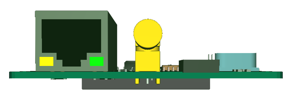
This is the Ethernet board 3D from front. This 3D model is a bit ruff, but it serves its purpose and looking at this I realize that the RJ45 connector is to high. This is not critical as I can adjust hight by extending the pins to the next board (not shown) and use extended PCB spacers. But, I could also solve this by using a different RJ45 that is lower and positioned half way through the PCB. I could also just use magnets and remove the RJ45 itself which is common in some industrial solutions, but I prefer using a standard RJ45. The funny thing is that I was concerned about the antenna connector which also is on the edge – which means I have the same challenge with NB-IoT, LoRa and GPS antenna connectors.
The current board (rev 1.2) uses LAN8710 and looking at the chips I have decided to move to LAN8720 which is smaller, but looks easier to solder. But, I will order the LAN8710 board anyway since I have a few chips around.
I currently experiment with a Olimex board that use LAN8710 and the code is actually for LAN8720, so the chips are compatible. LAN8720 is a simplification of LAN8710. It will be interesting to know if I can manage soldering these QFN packages for hand because I have a few chips that I have avoided due to this.
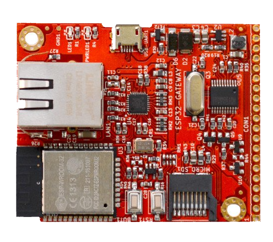 The Olimex board (shown above) works OK and add Ethernet and SD-Card + a few pins. Coding this rather straight forward, but I am a bit puzled as to why they don’t provide proper sample code. It is actually not much sample code demonstrating Ethernet – that said it is basically only the init that is different from Wifi. I use Arduino libs at present, but will switch to the full SDK later.