50A Driver Pin Layout

I still have a job to assemble a full 50A motor driver, but I want to set up the MCU with correct code first. I use IR2103 that will prevent short-cut, so we should be safe, but it is better if we have pins & IO ready. CubeMX is great for this and it also add in FreeRTOS and USB Serial. The later is important because I want a debug UI to operate the channels through USB.

CubeMX auto-generate drivers and configurations as well as producing a PDF report that is a good starting point. It also integrate directly with SW4STM32 (IDE) so you basically just press a few buttons and have your code running.

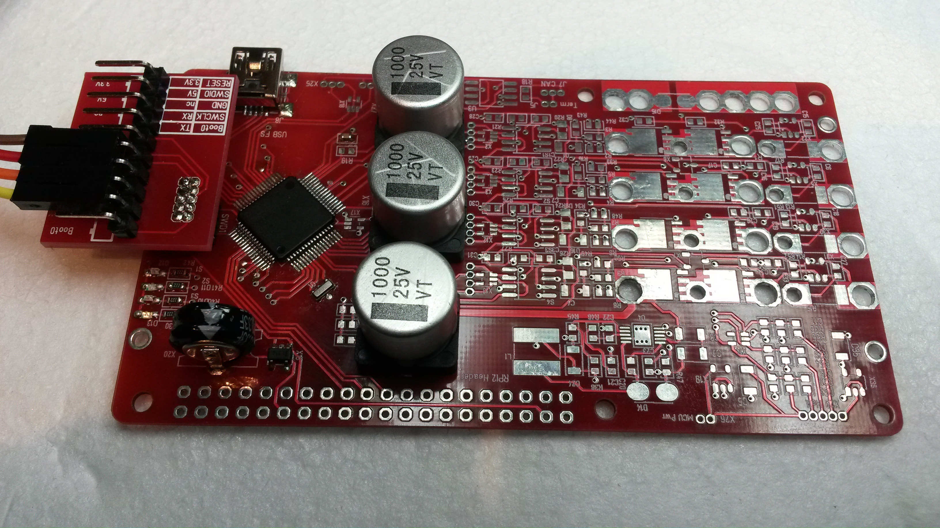
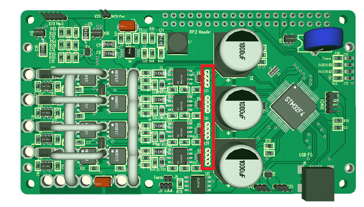
Just to remind everyone of the content on this controller:

  • STM32F405RG ticking at 168Mhz, 1Mb Flash, 192Kb SRAM
  • Rated for 60V at 50A
  • Raspberry PI Hat format enabling other boards to be added for more functionality.
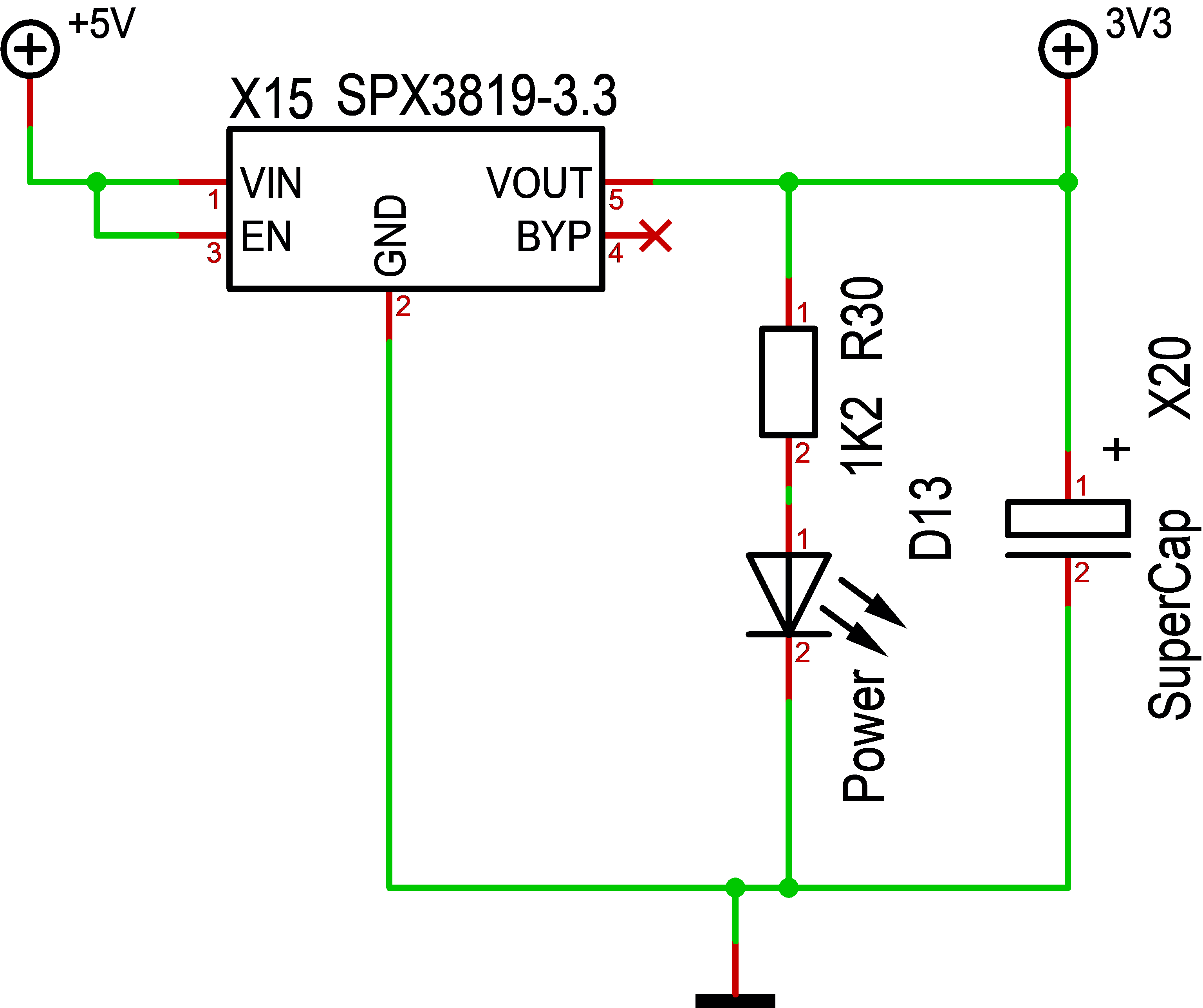
  • Separate PSU for processor
  • Supercap and motor capacitors on board.
  • USB Interface
  • CAN Interface
  • SWD
  • 2 x End-point connectors
  • 3 x Hall sensors
  • 3 x Status Leds
  • 4 x separate PWM channels
  • 4 x high-side current sensors
  • 4 x BEMF sensors
  • 1 x DC Input sensor
  • 2 x on-board temperature sensors
  • TVS on all signals between MCU and Driver

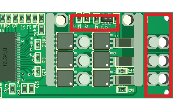
MOSFET’s are 60V rated for an insane 160A and 400A in pulse drain. Well above the 50A target of this board, but as I have shown though math current limit is also about power disipation. And to repeat myself – at present I have equipment to test ca 10A. I actually need to build some PSU’s for heavier testing.

It is a lot of low cost motor controllers out there, but this one is actually designed to sustain 50A as a constant load and it is one of the few universal controllers supporting stepper motors this size.

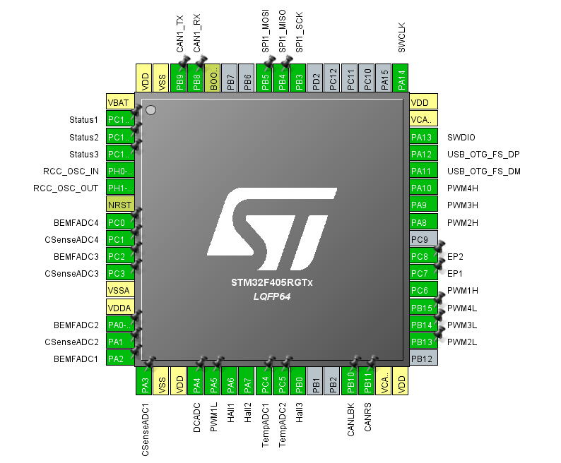
The following table show the pin layout and usage on rev 1.1 of the universal 50A Controller.

2 PC13 Status1 Status Led
3 PC14 Status2 Status Led
4 PC15 Status3 Status Led
8 PC0 BEMFADC4 ADC measuring V out on channel 4.
9 PC1 CSenseADC4 ADC Measuring high side current on channel 4.
10 PC2 BEMFADC3 ADC measuring V out on channel 3
11 PC3 CSenseADC3 ADC Measuring high side current on channel 3.
14 PA0 BEMFADC2 ADC measuring V out on channel 2.
15 PA1 CSenseADC2 ADC Measuring high side current on channel 2.
16 PA2 BEMFADC1 ADC measuring V out on channel 1.
17 PA3 CSenseADC1 ADC Measuring high side current on channel 1.
20 PA4 DCADC ADC measuring voltage in on driver part.
21 PA5 PWM1L Low PWM on channel 1.
22 PA6 Hall1 Hall encoder 1
23 PA7 Hall 2 Hall encoder 2
24 PC4 TempADC1 Temperature sensor 1
25 PC5 TempADC2 Temperature sensor 2
26 PB0 Hall 3 Hall encoder 3
29 PB10 CAN LBK See CAN.
30 PB11 CAN RS See CAN.
34 PB13 PWM2L PWM ch 2 Low – TIM1-CH1N
35 PB14 PWM3L PWM ch 3 Low – TIM1-CH2N
36 PB15 PWM4L PWM ch 4 Low – TIM1-CH3N
37 PC6 PWM1H PWM ch 1 High – TIM8-CH1
38 PC7 EP1 End Point sensor
39 PC8 EP2 End Point sensor
41 PA8 PWM2H PWM ch 2 High – TIM1-CH1
42 PA9 PWM3H PWM ch 3 High – TIM1-CH2
43 PA10 PWM4H PWM ch 4 High – TIM1-CH3
44 PA11 USB DM USB
45 PA12 USB DP USB
55 PB3 SCK1 SPI for backbone 42Mbps
56 PB4 MISO1 SPI for backbone 42Mbps
57 PB5 MOSI1 SPI for backbone 42Mbps
61 PB8 CAN_RX CAN RX
62 PB9 CAN_TX CAN TX


CHM-T48VB

Reading up on these machines I find a lot of praises about this series. I really like this machine with 58 feeders, but it will cost me close to 6000.- USD before I have it in Norway.

The reviews are all good. The main comment is on camera lighting. It can detect 0603 components, but struggle with QFN. It will take a while before I can order this, but I hope to have it in the pipeline at summer.

Ground Plane Broken

Bugger – checking ground plane integrity I realize that it is broken. The green areas have component grounding, but the 3D showed that it was connected – the real PCB is however not connected. I should have forced a track here to ensure that this was connected, but I will solder a wire on the back-side to fix this.

What happens is that the ground plane path is so thi that the CNC dropped it. This will cause BEMF3 to fail until I fix it.

Another note is that I might remove some filter components and do filtering in SW. I have plenty of MCU power available on this M4.

Ground Plane

I did the PCB for this motor controller before I moved on to do a lot of other Hat’s and added it to a batch as I ordered PCB’s later. I obviously did not spend much time looking over the design. Looking at the capacitors I realized that ground plane was broken between capacitors and ground in. It is connected though the long way around, but a few simple changes and it is directly connected as these pics shows.

The picture above is rev 1.1 where you see that orange and pink is not connected. On the picture below I have moved things around so we get a direct Connection. I see a lot of optimization options on this design.

This is not in the main current path so it is not critical, but I like as much of ground plane to be connected as possible.

Difficulities with headers

This is the 2nd unit where I have not added header yet. I tried to manually solder on the capacitors, but failed so I tried the IR heater and realized that the unit was to tall to go in with the header so I soldered the unit that did not have a header yet. Looking at the header pins I realize that I will struggle to get solder tip to those pins. This will require some thought because it makes the board very hard to manufacture.

One idea that I will try out is to replace the 3 x 25V/1000uF with 4 x 16V/1000uF. I actually think they occupy less space and hight all in all.

I tried soldering those capacitors with heat gun, but simply could not even get the paste to melt. This is the first time ever I actually was forced to use the IR Heater.

Out of connector space

It’s fun to assemble a Hat as complicated as a 4-channel Motor Driver the first time, but you need to be prepared for a few surprices. I spaced out 4 connectors to be able to test each channel better and the intention was to add JST Micro connectors. But, as I only used 1.27 headers on the 3D and not the proper package I missed out that the space to components on each side is to small (see red square). I will make this work, but a note to rev 1.2 is to modify this.

And while we are at it – I have not added a single led on the 60V DC/DC PSU – very annoying since I power the MCU and Driver separately.

Don’t worry – it will be plenty of comments that need to go into Rev 1.2.

This board is the first of this design, but I tagged it Rev 1.1 because it is a diversion from rev 1.0 on the smaller 30V/20A design.


To tall components

I am quite pleased with the 1000uF and supercap design, but they are to tall for the 8mm spacer between boards. I will have problems stacking other board on top as they risk shorting the boards. I can just about get one of the smaller super-caps, but no chance for the 1000uF capacitors.

The easiest solution is to just replace the spacer with an 11mm PCB spacer that is perfect for the connector anyway. I do however have an additional challenge with the heat-sink coming on botton. This Board is ok by itself, but I need to adjust the mechanics to be able to stack it.


Failing MCU

I have always added a minimum on components on my design and on the 60V/50A Motor Driver I have 4 PSU of which 3 is SPC3819. So assembling this I only mounted a minimum to get the MCU ticking and got a surprise – it would not tick. Soldering off MCU, putting it in tester and it ticks perfectly. Soldering it back on and no. Ok, soldering a 2nd unit and I have the same problem. So, I finally added the super-cap to the PSU above which feeds the MCU and voila – they both work.

This circuit mistake is pure stupidity from my side. I assumed it was so much capacitance that I could drop the standard 10uF on the output not considering the fact that without anything the smallest dip in voltage will be exposed to the MCU causing havoc. More important, I think I need to modify my designs to have a 10uF close to power input on the MCU’s from now on.

The four PSU’s are:

  • 3.3V from USB (above)
  • 12V for gate drivers (DC/DC)
  • 5V for Hall circuits
  • 3.3V for non-MCU parts

The MCU part have the supercap and can feed from the 12V. But, even on the 5V input from USB – no capacitor. I see the mistake – it would have a cap there if it daisy-chain and feed from the 12V, but not if it feed from USB. I don’t think the designer was fully awake the morning he drew this 🙂

The purpose of these PSU’s are that the 5V on the RPI buffer can feed the MCU without being connected to the 60V chain of destruction.

R30 has the wrong value in schematics – I always use 2k2 on leds.


3-Phase 50A Modifications

I want to attempt a few changes on this 3-phase controller.

  • Remove the 3rd current sensor marked in red at top.
  • Remove the output holes at right and take the output directly from between the MOSFET’s.
  • Add at least 1 temperature sensor. I can use more space between MOSFET channels and maybe squeeze in the temperature sensors here. I would prefer two, but one is ok.
  • Modify power input so one wire comes at top and one at bottom. This enables me to easier mount the capacitor directly on the wires.
  • Strengthen power paths to support 50A++. The MOSFET is capable of 160A and 400A phase currents, so it is all about heat dissipation and current paths.

I have no experience with these MOSFET’s, I still lack experience with the temp sensors, current sensors and 2-3mm wires etc – so it will take a while experimenting on the 4 channel before I am ready to move on this smaller and more specialized design.