CAN Adapters

I have 2 CAN Adapters at present. One is the low cost USB Adapter and the other is the XPortHub.

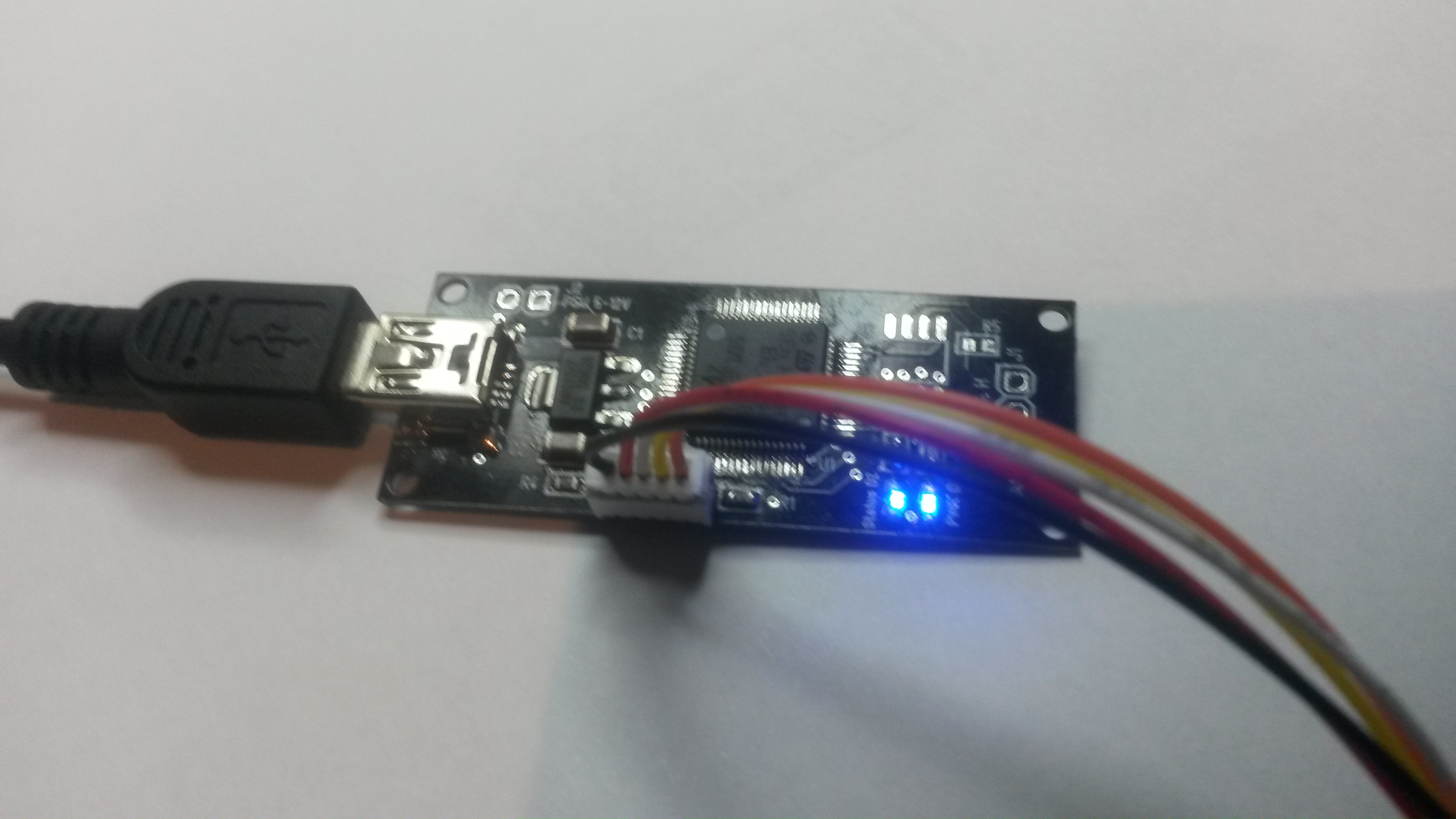
The picture above show the smaller, single channel USB to CAN Adapter.

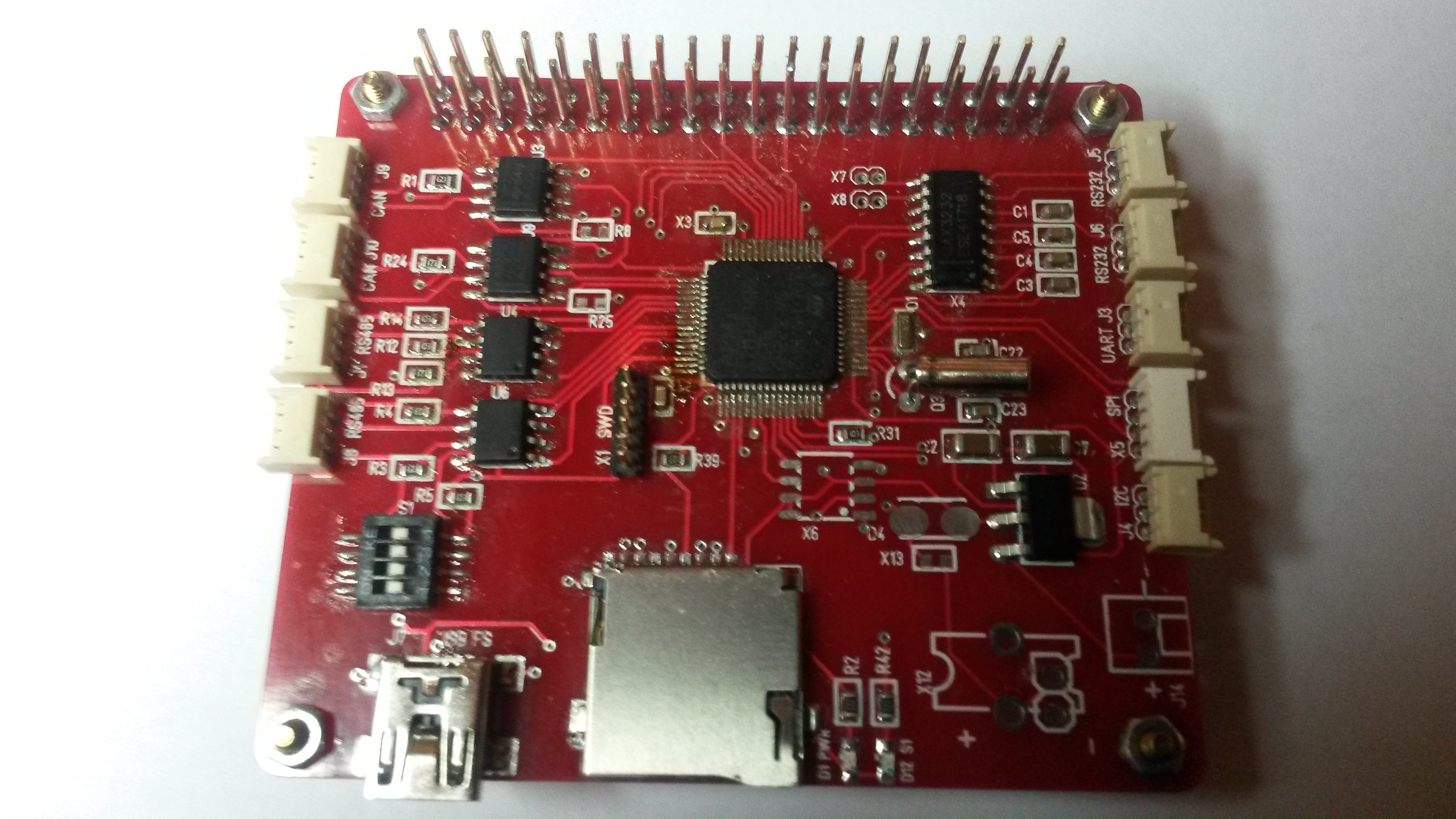
The picture above show the more powerfully XPortHub that provide USB, CAN, RS-485, RS-232, UART, SPI and I2C channels.

The USB to CAN adapter is designed as a low cost adapter while XPortHub is designed to be a component in a modular control system. But, they are both excellent USB/CAN Adapters.

The CAN ports offered are CAN-HS (High Speed). It actually also exist a CAN-LS/FT (Low Speed or Fault Tolerant). The HS bus uses 2 wires, while the FT version uses 4 as it includes + and – and schemes for communication if one of the twisted pair lines break. This is however rarely used as most systems prefer to just use 2 CAN ports for redundance


CAN Arbitration

One of the things you need to be aware off as you design (or use) a CAN based protocol is how arbitration works and how it can be used to your advantage or create a timing bug if it used wrong.

CANbus consist of a 11 or 19 bit ID field at the head of a message. These bits are part of what is called the “arbitration field” where 0 is a “dominant” bit. As a device want to send a message it waits for the bus to be idle and then start sensing on a clever timed scheme. At this point our device might be one of many that start sending, so we read back what was sent on the bus. If one device send 0 and another 1 the electronics will work the way that 0 becomes dominant. The device that send 1 and read 0 will stop sending and the device sending the lowest id field will at the end complete it’s sending. This means two things:

ID=0 is a very good candidate for a high priority alarm message.

Some messages will be delayed due to the bus being busy and their ID did not win the arbitration. This means that as you want to send a message every 100ms that message might pop up much later than you expect if you have a busy network and accidentally many devices that want to send.

This arbitration delay can lead to some very random and frustrating timing issues if your CAN protocol is designed wrong as in not handling this well. Messages simply get delayed.

Do however remember that the main reason for messages being delayed usually is noise on the twisted pair causing CRC errors.

How do you see these things? The answer is that you need an advanced CAN logger and CAN Protocol Analyzer that tend to cost a bit of money. This is easy to detect scanning a log as you will see this as dense message sequences in the log. A proper analyzer will show you a graph or alarm you about arbitration situations of some length, but these tools sadly cost money.

Remote PSU Switch

The 50A Motor Controller have 2 separate PSU feeds – one for the MCU and one for the Motor driver. This allows me to power the MCU and let this switch on/off power for the driver part.

Simply create a 48V/50A PSU Controller Hat as illustrated on the drawing above. I like this idea, but I don’t like the idea of letting 50A pass anything on it’s path. I would need a large relay for this – or do I?

I have a bunch of these 20A relays that actually are very small. I am toying with the idea of creating a Hat with 3 to 5 of these. Basically I just combine PSU sources to get higher currents.

I am a bit puzzled by the marking of these as they rate 125VAC, but only 24VDC. I actually need 48VDC, but these only cost a few cents so I can test. I have larger ones that can take 230VAC and these relay boards are very handy regardless.

But, But, But… having to wire 50A through another board is not nice – so I am thinking several PCB’s here – I obviously would like relay boards in Hat formats, but I would also like a Hat capable of switching external power paths – meaning I put the relay on a separate board for higher current solutions.

Actually it already exist low cost relay boards driven by ESP32 which is excellent for doing this job. I like to have my systems wired and only use Wifi if I must, but the good thing about the Wifi option here is that I can buy someone else’s board for a change.excellent for doing this job

This is only a brief idea at present, but having relay boards and options as part of a modular control system is a must.


Testing a 50A Motor Controller

One of the good things about MC4X60V50A (or steampunk controller if you like) is that MCU is powered separately from the MOSFET driver part. This enables me to use a USB, power the MCU and write test code without worrying about the 3KW driver part.

For actual testing I can settle with smaller motors to test logic. I have plenty of Nema17 rated to ca 2A, one 3-Phase rated 30A, another rated 15A and I have even ordered one rated 90A max. The challenge is more that I at present only can support max 30A from Lab PSU’s. But, that will have to do for now.


Worn out Pick & Miss Machine

I decided to use the IR Heater for this board, so in the process of manually applying paste and placing components. Got the large components on, but still miss the 0603 o-fun. This is much harder work than it looks sitting there trying to get components you hardly can see placed.

Actually have to rest my right hand – lol.

Someone buy me a pick and place machine please! I know – I am just complaining because I can’t afford a Pick & Place Machine right now! But, I think the worst is done now – all those SC75 and SO23 things are on there – those buggers are the worst because I can hardly see them so you have to work through magnifiers all the time.

50A Driver Pin Layout

I still have a job to assemble a full 50A motor driver, but I want to set up the MCU with correct code first. I use IR2103 that will prevent short-cut, so we should be safe, but it is better if we have pins & IO ready. CubeMX is great for this and it also add in FreeRTOS and USB Serial. The later is important because I want a debug UI to operate the channels through USB.

CubeMX auto-generate drivers and configurations as well as producing a PDF report that is a good starting point. It also integrate directly with SW4STM32 (IDE) so you basically just press a few buttons and have your code running.

Just to remind everyone of the content on this controller:

  • STM32F405RG ticking at 168Mhz, 1Mb Flash, 192Kb SRAM
  • Rated for 60V at 50A
  • Raspberry PI Hat format enabling other boards to be added for more functionality.
  • Separate PSU for processor
  • Supercap and motor capacitors on board.
  • USB Interface
  • CAN Interface
  • SWD
  • 2 x End-point connectors
  • 3 x Hall sensors
  • 3 x Status Leds
  • 4 x separate PWM channels
  • 4 x high-side current sensors
  • 4 x BEMF sensors
  • 1 x DC Input sensor
  • 2 x on-board temperature sensors
  • TVS on all signals between MCU and Driver

MOSFET’s are 60V rated for an insane 160A and 400A in pulse drain. Well above the 50A target of this board, but as I have shown though math current limit is also about power disipation. And to repeat myself – at present I have equipment to test ca 10A. I actually need to build some PSU’s for heavier testing.

It is a lot of low cost motor controllers out there, but this one is actually designed to sustain 50A as a constant load and it is one of the few universal controllers supporting stepper motors this size.

The following table show the pin layout and usage on rev 1.1 of the universal 50A Controller.

2 PC13 Status1 Status Led
3 PC14 Status2 Status Led
4 PC15 Status3 Status Led
8 PC0 BEMFADC4 ADC measuring V out on channel 4.
9 PC1 CSenseADC4 ADC Measuring high side current on channel 4.
10 PC2 BEMFADC3 ADC measuring V out on channel 3
11 PC3 CSenseADC3 ADC Measuring high side current on channel 3.
14 PA0 BEMFADC2 ADC measuring V out on channel 2.
15 PA1 CSenseADC2 ADC Measuring high side current on channel 2.
16 PA2 BEMFADC1 ADC measuring V out on channel 1.
17 PA3 CSenseADC1 ADC Measuring high side current on channel 1.
20 PA4 DCADC ADC measuring voltage in on driver part.
21 PA5 PWM1L Low PWM on channel 1.
22 PA6 Hall1 Hall encoder 1
23 PA7 Hall 2 Hall encoder 2
24 PC4 TempADC1 Temperature sensor 1
25 PC5 TempADC2 Temperature sensor 2
26 PB0 Hall 3 Hall encoder 3
29 PB10 CAN LBK See CAN.
30 PB11 CAN RS See CAN.
34 PB13 PWM2L PWM ch 2 Low – TIM1-CH1N
35 PB14 PWM3L PWM ch 3 Low – TIM1-CH2N
36 PB15 PWM4L PWM ch 4 Low – TIM1-CH3N
37 PC6 PWM1H PWM ch 1 High – TIM8-CH1
38 PC7 EP1 End Point sensor
39 PC8 EP2 End Point sensor
41 PA8 PWM2H PWM ch 2 High – TIM1-CH1
42 PA9 PWM3H PWM ch 3 High – TIM1-CH2
43 PA10 PWM4H PWM ch 4 High – TIM1-CH3
44 PA11 USB DM USB
45 PA12 USB DP USB
55 PB3 SCK1 SPI for backbone 42Mbps
56 PB4 MISO1 SPI for backbone 42Mbps
57 PB5 MOSI1 SPI for backbone 42Mbps
61 PB8 CAN_RX CAN RX
62 PB9 CAN_TX CAN TX


CHM-T48VB

Reading up on these machines I find a lot of praises about this series. I really like this machine with 58 feeders, but it will cost me close to 6000.- USD before I have it in Norway.

The reviews are all good. The main comment is on camera lighting. It can detect 0603 components, but struggle with QFN. It will take a while before I can order this, but I hope to have it in the pipeline at summer.

Ground Plane Broken

Bugger – checking ground plane integrity I realize that it is broken. The green areas have component grounding, but the 3D showed that it was connected – the real PCB is however not connected. I should have forced a track here to ensure that this was connected, but I will solder a wire on the back-side to fix this.

What happens is that the ground plane path is so thi that the CNC dropped it. This will cause BEMF3 to fail until I fix it.

Another note is that I might remove some filter components and do filtering in SW. I have plenty of MCU power available on this M4.