AD5231 Digital Potentiometer

I showed the MOSFET driven resistor array earlier and while searching for digital potentiometers I found 2 that are SPI based on 10K. One is the MCP41010 with 255 steps, but the one I really liked is the new AD5231 with 1024 steps. They exist in 10K, 50K and 100K versions and provide a far more elegant solution that a discrete array of MOSFET’s and resistors.

AD5231 cost ca 4.- USD, but it contains memory for power up, support both 3V, 5V and +/- 2.5V and a lot of advanced functions. I have a few analogue designs I want to dig into with this, an analogue PSU is one of them.

Wiring the 50A controller first time

I started to mechanically assemble the 4 channel 3KW controller. One note is that 2mm wire is easy to work with, while 3mm wire is very hard to get right. In fact, to assemble this it might be better to design with 2x 2mm wires than using a 3mm. I have not started with components yet, I am just making the mechanical wires ready. All in all it went easier than I feared, but I still have some wires to prepare in the middle so we will see how it goes.

Just to remind everyone – the 2-3mm wires are to support 50A out.

As can be seen on this pictures – these boards have a major design flag. You can see the square pads that will solder to the pad’s of the wider SO8 MOSFET’s, but what is missing is the array of went holes to the back-side. This should have connected the MOSFET’s to the back and used the ground plane as base heat-sink + enabled us to connect a heat-sink that was connected to the MOSFET’s. Without this the MOSFET will heat up far to fast, so I am not going to attempt 50A out of this yet. But, we should still be able to manage 20-30A out. For now I just want to assemble and test the unit. I lack both motors and PSU for heavier load testing anyway yet. I will send for a modified revision as soon as I have some experience from this.

What I am most curious about here is to test the new super-MOSFET’s supporting 60V and 160A with an insane 400A pulse drain + temperature sensors and current sensors. I have a ducted fan 12V/30A + a 12V/15A motor, but I need to increase my arsenal of test motors.

Programmable Function Generator


Assuming I create one Hat with AD9851 and a second with an analogue, programmable PSU and a 3rd with an amplifier this project suddenly becomes very realistic. I doubt that I can get all I need on one Hat and an analogue low noise  +/- 24V PSU is actually so awesome that I would like one anyway.

AD8008 is a SO8 size amplified that support 5-15V and ca 100mA up in high frequencies. I will need a different solution for +/- 24V out, but I will return to the amplifier Hat.

I might also use AD8008 for high frequency 3.3V/5V signals and simply settle for <300Khz or something on the more powerfully amplifier focusing on audio channels.

I need to find time for some breadboard experiments before I start on this + I need to look for solutions to higher frequencies on the amplifier Hat. It will be much cheaper to just go and buy a 2-channel DDS ready boxed, but where is the fun in that 🙂

Analogue, Programmable PSU

This weird circuit is a programmable, analogue PSU. It is basically only a LM317 and an array with resistors and MOSFET’s so I can program the voltage out by selecting a combination of 10 resistors. This is not straight forward, but I can at least Select 10 preset values. In addition I use an ADC to measure actual voltage out. I need to calculate resistor values, but this will work just fine and solve my challenge with how to get a programmable PSU for a function generator.

R7 and R12 decide the max output voltage. By switching on/off MOSFET’s you change the voltage divider adjusting LM317 and hence the output voltage. This is not the most elegant PSU, but it is analogue avoiding the challenges with switching noise on a DC/DC regulator.

To get a negative voltage I do the same with LM337 and a different MOSFET array, but I will get an additional challenge I need to divide input voltage. Assuming I have 24V in I can establish ground out on 12V and have a circuit that output +/-12V. To do this I also need to ensure that signals to the MOSFET’s have correct voltage using the new ground as reference. I think I can get away with that by using the new ground as ground for the MCU and AD9851 as well.

I use 2N7002 in the example above which cover 60V in SO23-3 package, but you can use any N-channel MOSFET. LM337 needs to be associated by P-Channel MOSFET’s I think. This circuit is excellent for a breadboard test.


Function Generator Hat

I need a function generator and I like AD9851. What I really would like is a Function Generator Hat with programmable +/- voltage like the diagram below:

This is not impossible, but the DDS, Amplifier and Programmable PSU on a small Hat is not realistic. Or – well – I need to think about that one. In the meanwhile I decided on a compromise as follows:

I can easily switch between 3.3V and 5V using SPC3819 and that alone is a start. AD8008 amplifies the signal at high bandwidth giving 100mA out which is decent and AD9851 deliver a very decent 70Mhz function generator. This should be very realistic to get in a Hat format.

I seriously would like to program +/- 10V or similar out, but I need to work on that. It is possible, but I have 2 challenges – (1) is the noise of a DC/DC so I need to dig into a programmable, linear PSU. (2) Amplifier at high frequency, but I wonder if I am ok with <1Mhz at this functional level. So, in short – the programmable amplifier can be a separate Hat.


30V 20A++ Driver

This is the backside of the 30V x 20A Motor Driver and the red lines are the main power paths. The lower left one is the + path, while the top, angeled is GND. The later will be merged into ground plane so it get a bit extra help. But, these are the paths I expect to be the weaker links that will limit total power on the driver board. So I want to prepare adding 2-3mm wires soldered straight on the paths to assist. Keep in mind that every channel here is rated 30V x 20A, so if we use 4 channels individually we could push 4 x 20A = 80A. It is no way we can sustain 80A, but if we run 2 x DC motors the extra lane support could give us 2 x 20A ++.

As I said – this is a free option as I just have to open those lanes for soldering to make it easy to strengthen those paths. I will also add that the heat-sink and 2mm thermal padding comes straight on top here basically cooling the PCB directly, so it will be interesting to see what I can get out of this one. These lanes sustained 10A no problem, but that said – it’s a huge difference between 10A and 20A. Once you hit the point where the PCB starts heating up it goes fast.

New 30V/20A Motor Driver

The first draft of rev 1.1 of 30V 20A Motor Driver. The differences are that I replaced the DC/DC with a 78M12 (linear regulator) for simplicity and cost, replaced INA210 with INA193/INA194/INA195, added 2 temperature sensor on-board and replaced connectors with te smaller JST Micro connectors. I also combined 3 connectors to one. I also removed all the extra drill holes as I will use a heat sink the same size as the PCB and attach caps on top.

I had to space out the 4 channels to get the temp sensors in between. I still have some work on this 80x40mm board, but I am a bit surprised over how much space I suddenly have. The original design target for this was 15A, but I am increasing that to 20A and I will widen the main power lanes to support a heavier total load.

I am not finished with this, but I am quite happy with the draft so far. I still lack support for the 1-2000uF capacitor that need to go on top because heat-sink is on bottom. 

Just to remind everyone

  • 4 separate Half H-Bridge channels that can deliver 30V /20A. Many of the MOSFET’s are capable of more, but the PCB will overheat at some point. The previous design had no challenge with 10, so lets see.
  • 4 high side current sensors
  • 4 BEMF sensors
  • 2 temperature sensors in between MOSFET’s
  • Separate Supercap to protect and keep MCU alike through power cuts.
  • Hall sensors w/Leds
  • End point/Resolver input
  • RS485
  • Powerfully STM32F405RG
  • Design is 600W (30V x 20A) with 360W (24V x 15A) as very realistic.

Applications

  • Bike Motor Driver
  • DC Motors
  • Solenoids
  • Stepper Motors
  • 3-Phase Motors

I like this controller due to it’s smaller size and simplicity compared to the 60V x 50A one. 20A out on PCB lanes might be stretching it a bit – we just have to test and see. And yes the PSU is 36V, but some of the MOSFET’s are 30V hence this limit. I probably could decrease the length to 70mm, but I don’t see the point + the heat-sinks I plan to use are ready made on 80x40mm making assembly very easy.

The only thing I lack is the faster SPI bus and interface to other boards. I can easily widen the board to 55mm and add RPI header and drill holes, but I am thinking more in the direction of adding a specialized adapter just so I can get easy access to LoRa, GPS, NB-IOT, Wifi etc.

HMI Designer & Browser

This is an early beta of the HMI Designer. The idea is that you draw your HMI displays, save them as XML and then send them to a HMI Browser. The Browser will execute the graphics and send back user events allowing a system with no knowledge of HMI, how or what to make use of advanced HMI capabilities.

More important is that it will support Windows, Linux, iOS, Android and customized embedded solutions without the programmer needing to dig into specialized HMI design skillsets.

HMI Broweser is not so unlike a Web Browser, but it is designed to be a HMI for an embedded solution and contains pre-made graphics components and infrastructure dedicated for complex SCADA systems.

All code done in C/C++ with Qt as base.

Model Train System

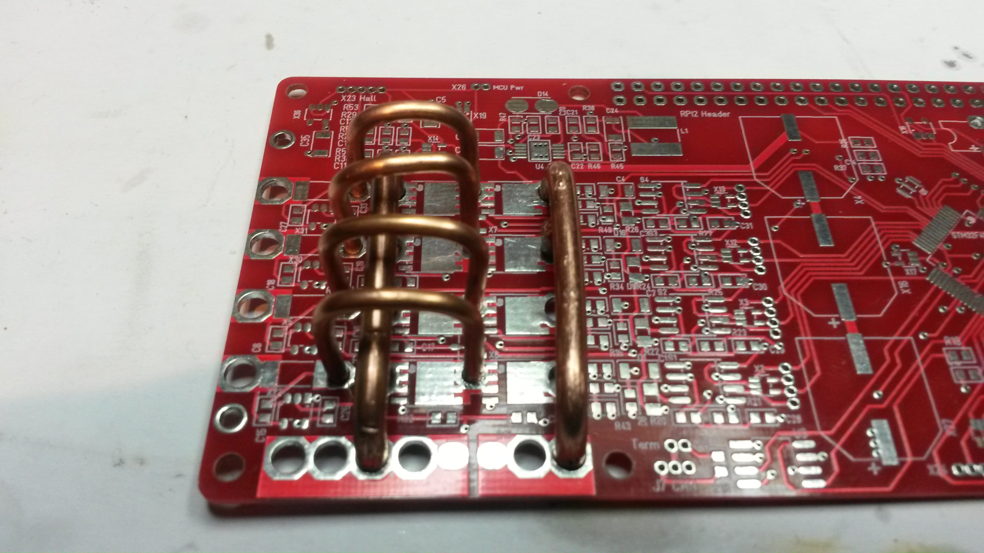
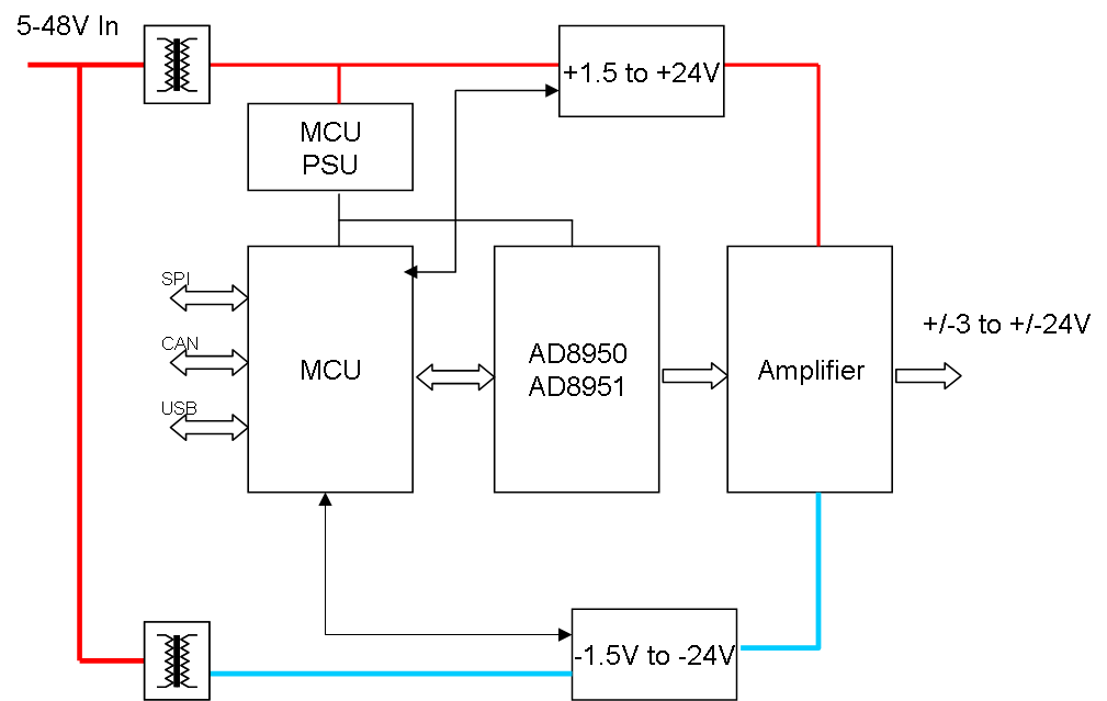
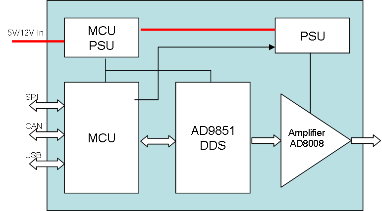
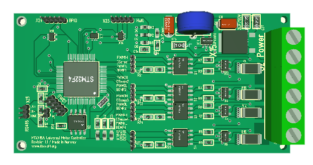
This was my first project that got me started on electronics again. The initial design did not work at all. It used an STM32 on one side and ESP-03 on the other which created too much interference + I had selected the wrong type H-Drive. The MCU and PSU design did however work well and was re-used on the second design based on ESP32. This one failed on a detail in the datasheet I had overlooked – not all IO pins are output. The main PCB is pictured below.


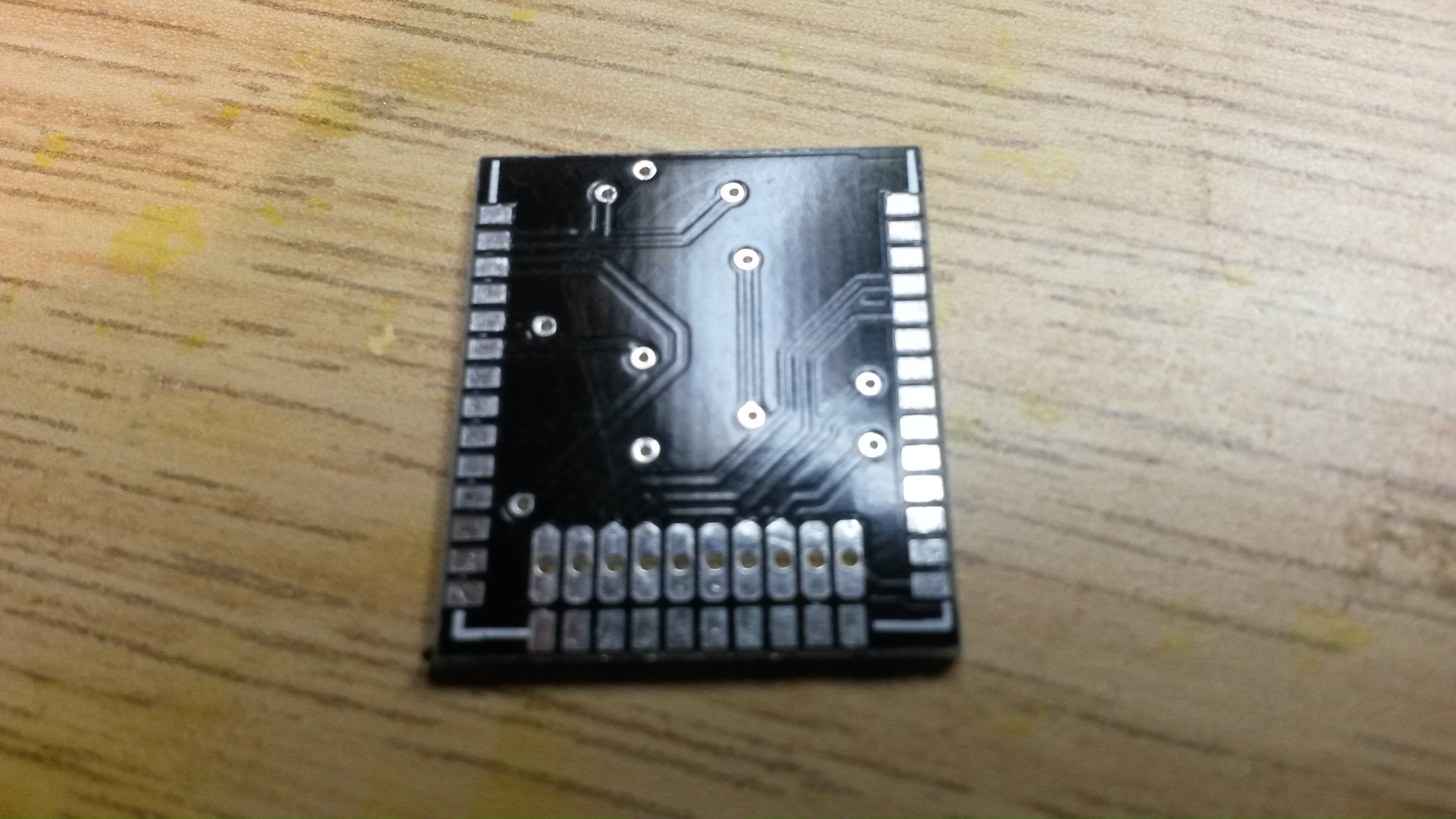
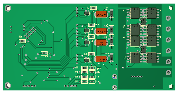
The backside is a bit special since it will only hold a single component ESP32. This is basically just a ESP32 with a PSU and a H-Bridge. I have drafted a New Controller, but it holding back a little investigating the position system that would change this from being a Remote IO toy to be an automated Train system.

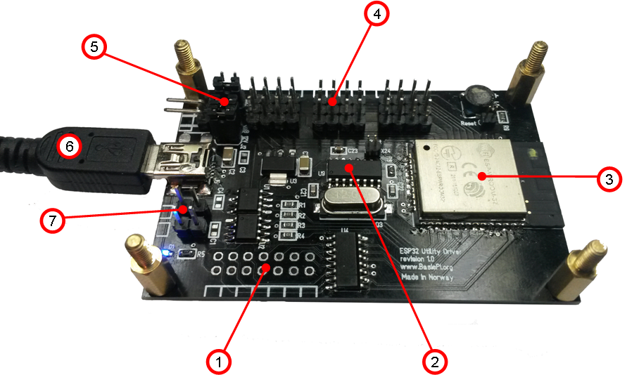
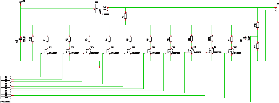
This is the intended utility driver to enable control of other things. It was on this I discovered the IO mistake as I only have 8 and not 12 servo ports here. To move on I actually plan to use my new modular control system because it is so much more flexible. But, I will probably still maintain these small all-in one controllers based on ESP32. This worked excellent expect for the surprise on on 4 of the ports.

The main challenge on this project was however that I failed to find a position system that would work. The initial attempt was to triangulate on ultra-sound and yes it works, but it’s no way to get required components into a small model train cockpit. The second attempt was to triangulate on radio strength for Wifi and Bluetooth. And again – yes it kind of works, but it is far to inaccurate.

The third method was suggested by a friend and might just work. He suggested using a camera in the ceiling and recognize model train positions that way. I figured that if I use a IR led to send info I can identify train and position.

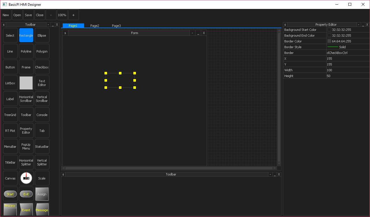
Changing the layout of the control system is easy, but I also needed to add a programmer. The intention is that these control systems will be programmed through Wifi, but we need a method to download the bootloader the first time.

I plan using OpenCV on a Raspberry PI with Camera for image processing, but this is an area where I am on thin ice. I know this should work, but I have little experience with image processing so this will be a new.


HMI Block Diagram

This diagram illustrate the HMI solution the way I am planning it. I would like one external RS485/UART so I can attach the display to any embedded solution. CAN, USB and SPI Backbone is mandatory. And I think SPI Half Duplex will do fine over max ca 50cm that we talk about here. SPI is also straight forward as it basically only will be a small 50 cent MCU on the add-on modules. I could even use full SPI in this case as we always will be talking to the main MCU and CS pins would solve the issue with knowing what module that I communicate with since these cheaper MCU’s don’t have an id number.