High Precision Posision System

This board can be purchased from Sparkfun for 215.- USD and is basically a breakout board for ZED-F9P from ublox. ZED-F9P can be purchased for 148.- USD in quantum of 10 units, but I only wanted two of these boards for now for my robot project.

What is important with this is the 10mm precision on the GPS. You are reading right – 10 milli meters (1 cm) accuracy. This is also why it is so pricy yet, but I expect it will get competition as we move forward and drop in price.

I have not tested this yet, but to achieve 10mm I will need two of these and set up a RTK system. RTK means you have (1) GPS on the vehicle and a (2) a second GPS on a fixed base station. As the base station know it’s position it can measure error in position caused by athmosferic conditions or weather and send that as correction data to the mobile unit. This is stated to be working for up to 50km, but I am happy with 5-10km as that is the practical range of LoRa units.

Myself I will only be running a small robot or garden machine around mostly for position testing.

I will return to this unit later. For now I want to focus on my HMI project + wait for better weather 🙂 because I basically need HMI for everything I do.

BSA – PLD Events Quick Guide

This example is a valid Plain Logic Diagram. Since the start and exit symbols are drawn on the same diagram this will count as a single diagram then it is re-used. It will be a block with 3 entry points and 3 possible events. Ignore the fact that Start3 and Exit3 is a separate diagram – if they are drawn on the same page they are seen as one. Also notice that I have added a circle and a circle with cross adapted from UML State Diagrams.

This next diagram (above) adds in a formal state definition as drawn in SDL (Specification and Description Language). The “operation” represent something we do – mostly sending an outgoing event/message. State will wait forever for Event1 or Event2 to happen. All other events are ignored. Event1 and Event2 only visualize the events we are waiting for. PLD do not require you to be so formal in defining your state-machine. State do however have a second function as it act as a goto-label. If you rename one of the exit symbols to the same name as “State” it will goto that state and in effect loop.

Events and Operations can be visualized in 2 different direction and with a color band to differentiate various protocols. These are only visual gimmics to help readability of a diagram.

PLD allows some simplifications. The first is that you don’t need that State symbol if your not going to use the goto functionality. You can simply add the events straight on the operations or any other symbol. This does the same, but simplifies the diagram a bit.

This next diagram (above) takes it all out as we display text only, not the events symbols.

This last one assume you call a function foo() wich will return Ok or Error. PLD allows events to be:

  1. Static, meaning they are hard-coded with  jump to a error-handler diagram.
  2. Optionally, meaning they have a default behavior the user can override.
  3. Mandatory, meaning the user MUST override.

Error and Timeout are usually coded as Optional, while OK is Mandatory.

This allows you to code advanced diagrams with error processing, but avoid that error handling takes over your diagrams.

Visual Studio MFC

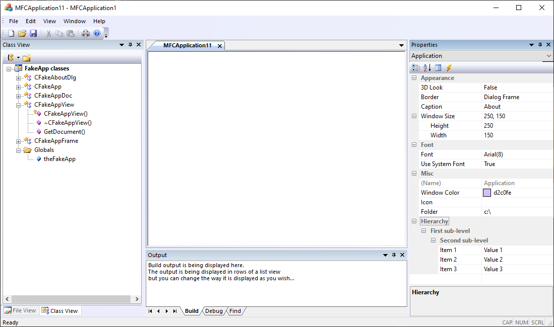
This is just an auto-generated demo (new application) using Visual Studio/MFC. I use Visual Studio Community so you can download this and try for yourself. I switched from DOS to Windows back in early 90’s using Windows SDK and C at first – I remember the day I got my hands on Visual C++ 1.0 and the first version of MFC – it was a big difference. The best part was the debugger that set a new standard.

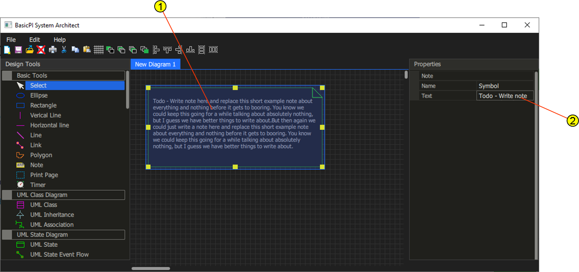
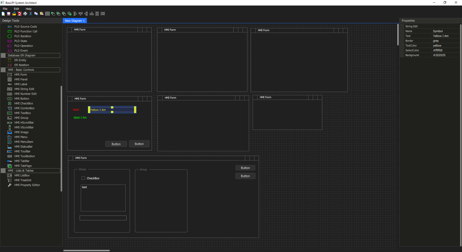
The content of the views about are demos – not functional, but the components are very real. You see a TreeView at left and a very good Property Editor at left + what you don’t see is a very good docking system. The app mimic an earlier version of Visual Studio.

Graphics in MFC is GDI by default, but you can use GDI+ with a trick – meaning modern precentation graphics through CPU.

Comparing MFC to Qt I would chose MFC any day, but Visual Studio only have C#/WPF that can compete with Qt/QML.

And as for MFC – I have used this for years as a Windows GUI developer, but it is few that uses this today – firstly it has a steep learning curve so few know it. But, Microsoft don’t focus on this anymore sot it is more or less abandoned. It does not receive the wealth of new components and infrastructure as .NET does.

Comparing Qt/QML to .NET/Core + WPF – I don’t know. C# is much easier to develop with than QML, but I have never dug into the WPF side. The reason I currently work on QML is the access to the GPU’s. QML is easy to work with on graphics, but bindings to C++ makes it difficult unless you want to develope everything in JavaScript. The main drawback with QML is that you don’t get a flying start as the one above – but, that will change soon.

MFC brings back many good memories about things that worked as expected – I will not claim that it is easy to code in, but it is no worse than Qt to be gentle.

The challenge however is that this is Windows Desctop only and for that it is great – but, applications these days needs to be precent on Web, Windows, Linux, iMac, tablets and phones – and it will be interesting to see if Qt/QML delivers on those.

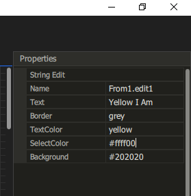
The demo above have some important learnings – Wizards & Templates to get started is worth a few days, but their not the ones getting the job done as you work day by day, month after month on a system. The Property Editor is a good source for ideas, but not everything is perfect. I will do better. As for docking system – Wait & See.

ST/STM32 SW Quality

I have written about this issue before, but ST never fail to suprice me on their SW quality – crap that don’t work: Bugs, bugs and bugs!

I updated STM32CubeIDE to version 1.6.0 yesterday and discovered that the IDE fail to load the images – I had to default to STM32-Link Utility to be able to load the image. Reading on other peoples work I see that I now need to download OpenOCD.

I wanted to test a USBCAN created with STM32F105RB and auto-created a project using the newest HAL driver from ST – guess what – it does not compile, so I tried 1.8.2 and it does not compile, but finally 1.8.1 compiled out of the box – this is serious crap!

The third error is the USB. USB work straight up on other MCU’s, but not on STM32F105fRB – I can’t rule out that this is a HW fault yet, but I have this working on STM32F405RG so I think the answer is that I ditch STM32F105 from my designs.

Don’t take me wrong – I am a big fan of ST MCU’s, but I am a bigger fan of things that actually works out of the box and it’s been far to many critical issues with ST’s software quality over the years. This is not exacly the first entry I make about ST and their SW quality. They are not at the lever they need to be on!

STM32CubeIDE is great – they had one of the best debuggers I have seen. I use OpenOCD on different projects, so it will be interesting to see how this works out – but, ST’s debugger seemed to work much better with debugging on multiple projects – that was before they screwed it up. I actually re-installed from scratch yesterday as well. I will dig into OpenOCD latar,

BSA – Color Palettes

Setting up all the colors needed for controls is actually a bit of job because you need a set of colors for (1) Normal display, (2) Mouse Hover, (3) different states. In this case I show a button so I need Pressed. And for each set I need background, text and border etc. So, if you see only a few properties now – just wait.

I need all the properties available, but at the same time I don’t want to fiddle with them. So, what I will do is to set up a Palette system where you chose the value “Palette” meaning that colors are preset in a global paletter that support global themes. So if you want to change a color you can either change the Palette – in which case you change it for all objects, or you can set the color directly as shown above. In the later case you change it for “this” control only. But, at the end of the day I just want to drop in controls and not worry about fiddly details like colors – I just chose a theme for my application.

BSA – Text Edit 2

My previous entry raised the issue about how to edit multi-line text. The illustrations below show one possibility.

In this case I illustrate a description – something I want on every object. This is a normal property, but since it is a multi-line text it servers little purpose to display it on a few characters like a normal property. A possible solution is shown below.

As you expand the property to edit it I can pop out a small mini-editor to make it easier to edit this exact property type. As editing is done we collapse it back in. The only drawback is that we now need to expand the text field every time we want to read it – which make it less available/readable. But, it’s an idea.

BSA – Text Edit

This shows the Note – the Note is a tool allowing you to write text with a Note border around it and it can be linked to obkects with lines etc – a handy way to make comments.

However – how do we edit the note? (1) display the full note, while (2) display the property editor version – ok it will look better once I allow multi-line text in the editor, but that is not the point – how should we edit the content of that note?

The answer is straight forward – directly in (1)! Double click on the node and you go into inline edit mode. This is one example where editing in the Property Editor makes no sense because an inline editor will be so more awesome. And even better is that while we edit we can as well show specialized text tools and even capabilities to add images inside text etc.

BSA – Property Editor

Don’t worry – you will hear a lot about the Property Editor. The one you see above is yet a simple one. I am still using string edit for colors, but it works fine due to the nature of JavaScript. JavaScript accept colors in string format by name or #xxxxxxxx. (ARGB format). I will add a proper dialog option for that later – but guess what – I wait for BSA to generate that dialog for me 😊.

The top 3 lines for each HMI object will be standard – a display of what control this is, the local name and the full name – currently you see the full name only. The name of the control is “edit1”, but since this is located on “form1” you get “Form1.edit1” – or more correctly “From1…” since I have a spelling error 😊.

I currently lack a lot of properties here like x,y,width,height etc. I will also need options to expand category trees and sort properties. And well – I did mention specialized edit dialogs.

One of the most wanted is actually a multi-line text editor. I want this to expand using the full width so you get a mini editor and optionally expand into a full window if needed. Adding comments and having proper tools to do so is important.

The Property Editor is important because it enable me to easily and uniformly edit all details of a diagram. The alternative would have been to create dialogs for everything and use double-click etc. With a property editor you only select the component and change properties watching the changes apply as you change them. A Property Editor is however not ideal for every property – descriptions etc is one of them, but you also have information that needs a table presentation. Forms itself need a hierarchy tree so you can see a list of content and control appearance if controls are located on top of each other.

The options I have is to (1) use trees, (2) use pages and (3) use edit buttons where you pop into a specialized dialog. One of the pages I probably need is the event list and bindings for it – not sure – I actually plan an event selector as part of some diagrams, but every form and component are a source of events + how do I handle this before the diagrams are in place etc – I need to think about that one.

BSA – Dialog Design

I am reaching a point where my illustrations regarding BSA are more and more the real thing. Property Editor is now real so I can start edit the components and add properties. I have a few days work setting up correct properties and then I will deal with saving and loading projects and a few other outstanding issues before I am on to generating code. Or well – don’t worry – I have plenty of work left yet.

Keep in mind that BSA uses Universal Diagrams, so unlike other design tools you can draw multiple things on the same diagram. In the illustration above I have drawn multiple dialogs. Each dialog has a Name, each component have an unique name within that dialog. Each dialog only cares about the component located on top of itself – so it is perfectly legal and beneficial to draw multiple dialogs on the same diagram as I have illustrated above.

Only basic components will be build in as the next, big feature is component libraries created by BSA itself. For example standard dialog boxes, gauges etc – I did decide to use a HMI solution fuled by GPU’s for a reason.

I used to design HMI solutions as a profession some 25 years ago, but never jumped on to the web thing. Watching over Web developers making HMI’s I was stunned about how limited their tools was as I have never understood why web developement needed to be worse than classic desktop development. Since the illustration above is a specification I can easily generate it as a Web page, desktop or tablet design at my chosing – without the developer needing to worry to much about the details except one – screen resolution if you use tablets/phones as target.

Qt will deal with execution on multiple platforms, but I do get an extra challenge using Qt – Print Preview and Printing is far from strate forward with that framework, but I will deal with that later.

BSA – DataSource

A critical component for a HMI Frontend is “Data Source”, meaning where is data loaded and saver. HMI alone is worthless unless it is actually connected to something. This can be a remote Modbus device, a database, simple memory structure, file structures etc. BSA will provide the component, but the user must add the source behind this API in ordinary code. This means that if your GUI display the value of a memory variable you need to put this inside a data source so that the GUI is updated every time you change that variable. This also means that updating the GUI now becomes as easy as setting a variable.

Modbus (as an example) is just as easy – you bind a modbus variable to the HMI and as the HMI write you write to the device and as the device update a variable the GUI is updated automatically.

The only difference between the pure HMI version and the later versions is that PLD can use data sources and process data. For now that needs to be done in source code. But, this is still a close to no-code system once you deal with the protocols.