BSA – Importing Source Code

This first version of BSA will not have any capability to create anything than HMI, so we need to be smart about how we integrate source code. And the answer is straight forward:

  • We could parse the source and auto-detect interface functions and events – it is possible, but it will require a good parser and it would still be a challenge to get it right – how do we detect events etc. The Answer could be that we use an API and detect that usage. It is possible.
  • The alternative I like is simpler – I expect the developer to add Interface tags in comments. This is already done by tools like Doxygen, but I want code to be clean and comments to be readable – so what I will do is to parse tags that are formatted as proper comments – and we can generate them as well. This means I parse a definition of an interface from structured, readable comments and leave it up to the developer to ensure the specification and code to be in line.

Now – this will work for my IoT devices as specified in my previous entry and it will work for any manual code the developer want to create or use – they add the interface specification in code.

I am not against parsing source code, but I realize that is a larger task that I prefer to not dig into right now.

BSA – Including IoT Devices

A “device” is a definition in our system that can be visualized as anything you want – in this example I use an image showing two of my cards attached.

What is important is that this device have input and output events – in this case shown as PLD terminals. This is a mock-up diagram (not real) so the actual diagram will have a few more details. Is this a UML State Diagram or PLD? Actually it is a UML State Diagram, but I can draw the same in PLD – and both are used the same way.

What the diagram show is that we have 1 timer and 4 input signals while we have 8 output signals. A signal in this context is a unique name with parameters. The device might have far more than this, but this is what I decided to import of the API in this case.

Part of the definition is that (1) I give the device a name, (2) I give info about connection protocol, (3) I define the signal list I am interested in. The rest is a black box.

Assuming this is a Modbus Device it will mean we need to import or create a Modbus table. Each signal is then mapped to one or more Modbus registers and the Timer will do the polling. As we set signals we just write to a local storage, wait for timer to do a write and read, and as we receive values we trigger the out signals we want.

This is just a mock-up/early illustration, so the actual diagram will be better. The HMI Designer will have a simplified version of this – we do not include the diagram only define the device as a component. The drawback is that any signal processing needs to be done in code, but that is where we start. As we add diagrams later we will be able to do processing a bit more visual as part of the diagram. But, we will still maintain the capability to just do this in code.

And how do we do it in code? Simple – pick up your favorite code editor and manually create a module that uses the BSA API. You can then import this as a “black box” with only the IO signal list available. and just use it.

BSA – Timer Tool

Many solutions depend on something happening as a responce to time – it can be something you need to do 12 a clock Wednesday or every second, but to do so you need a timer object that can generate a signal on the requested time. This tool is needed in all diagrams in BSA for this purpose including HMI.

Assuming I want to read CPU Temperature from a device 10 times per sec – to do so I create a diagram with 3 objects – my device “device1”, a HMI screen with a label “label1” and a timer “timer1”. In the properties I configure timer1 to send a signal every 100ms. That signal is sent to device1 that as a response read CPU temperature and send this back. In the HMI device1.cpu_temperature is mapped to label1. Voila – we got ourself a temperature meter.

In the diagram above that is an actual BSA diagram you can see the solution. I have drawn timer1 and label1. In this case I used a Link Tool to create a line between them. The Link Tool is the base for many diagram line based links, but in this case it serves only as a comment to illustrate that timer1 is related to this label. Neither the timer or the link will be visible on the HMI. Timer symbol itself is formed as a start terminal/event that can be used in both PLD and UML State Diagrams.

A smarter solution would be to locate the timer on the device and only start/stop it from HMI to avoid extra trafic on the connection between HMI and device1. I will get back to how we join signals together later, but we basically declare device1 and specify how we communicate with device1 – once that is done the API for device1 will be available and can be mapped to objects in the HMI – no coding needed unless you want to.

A later version will allow you to visualize this in diagrams and do more than just passing events forth and back, but for that we either need to do some manual coding or UML/PLD active – fun for later.

BSA – HMI Tools

The table below shows the current list of tools in HMI Designer part of BSA. It is few common tools like lines, notes etc not listed here, but this is the basic collection. I might add a few tools as I see the need, but this will more or less be version 1.0. A main milestone is to be able to auto-generate dialogs I will use in BSA, so basically the first version of BSA will be used to generate parts of the next version. This is needed due to the amount of work with these dialogs, but it is also an important milestone and proof of concept. The next step will be to add gauges and more HMI controls in hundreds – or more exactly – the current list is build-in tools while I will open for add-in tools later.

HMI Form Stand-alone dialog/window.
HMI Panel Panel – square used for colors, borders or collections of components.
HMI Label Text label.
HMI String Edit String edit field
HMI Number Edit Number edit field
HMI Button Simple Button
HMI CheckBox CheckBox
HMI ComboBox ComboBox
HMI TextBox Multi.line text edit box.
HMI Group Group border used to group components visually.
HMI HScrollBar Horizontal scrollbar
HMI VScrollBar Vertical scrollbar
HMI Image Image.
HMI Menu Menu bar at top.
HMI MenuItem Single menu item or pop-up menu
HMI StatusBar Status bar at bottom of form.
HMI ToolBar Toolbar used to create tool banner at top. Can hold other components.
HMI ToolButton Button with Image.
HMI TabBar Tab Bar
HMI TabPage Tab page. Similar to panel, but invisible until selected in a Tab Bar.
HMI ListBox List Box
HMI TreeGrid Tree Grid.
HMI Property Editor Property Editor

Raspberry Pi PICO – RP2040

Having worked with computers in 40+ years I must admit that I sometime dig into nostalgia and look at vintage computers before I recall how little you got done and how much time things took. The world has moved on – and thanks for that.

RP2040 or Raspberry Pi Pico if you like is a fresh breath into MCU’s. Firstly it cost 4.- USD on a breadboard, but it’s content is a very impressive and fresh design.

  • Dual core M0 @ 133Mhz
  • 264Kb SRAM – 2Mb Flash on original breakout board.
  • 2x UART, 2 x SPI, 2x I2C, 16 x PWM, 3x ADC
  • And 8 PIO channels, 3 each on 2 IO processors.

Take into account that IO’s are capable of DVI, Ethernet as well as more standard IO channels and you start grasping the capabilities of this little MCU. It’s not old, but the number of projects are already very impressive and this is only the beginning.

And well – it does not surprise me that someone already ported Unix to this one.

Back to my nostalgic wimps – this one could actually have a keyboard, a mouse and screen attached and outcompete my first IBM PC clone with a factor…

RP2040 sets a new standard of what to expect from new MCU’s and at a cost of <4USD and I am confident it will make it’s way into many industrial designs – because the HW is one issue, but just imagine the amount of free SW and IO components that will pop up on this one?

BSA Platforms Supported

This table shows the planned BSA support. Windows, Raspberry PI and STM32 are primary development targets, but Linux is covered through Raspberry PI and Mac’s will be covered. Other platforms, specially on the BSP (Board Support Package) side will be added.

Platform BSA Designer HMI Browser BSP
Windows Yes Yes Yes
Linux Yes Yes Yes
Raspberry PI Yes Yes Yes
Mac Yes Yes Yes
iOS Yes Yes
Android/Tablets Maybe(1) Yes Yes
STM32 Yes
Other embedded Yes(2)

(1) I am unclear as to wherever it will be practically to support BSA on tablets and Android in general. Making code portable is one issue, but making the designer fit on a tablet with keyboard etc is a different issue.

(2) As per need and available resources.

BSA Grids

DataGrid and PropertyEditor is still work in progress, but the same PropertyEditor that is used in BSA will also be available as a component. The same goes to the DataGrid. DataGrid is a smaller grid designed to use inline edit. I will also use a virtual grid designed to visualize huge amounts of data.

I am not sure about “DataSource” yet. A DataGrid will need a connection to a data-source. This can be manual, a ram table, an external XML table or maybe a SQL database etc. The common way to do this is to provide an invisible componente “DataSource” that is reffered by components vidializing/editing the content. I will do something similar. It makes sence to have this as a separate component – I think.

PropertyEditor is excellent for editing a single row in a table or an object (class). If you have a SQL database the two components shown would provide a raw editor in no time. This alone is worth gold because it allow you to quickly create GUI interfaces to databases regardless of what format they are in – and most applications actually have a database or internal data-tables and structures of some sort. BSA also includes classic ER Diagrams to be able to support SQL based Relational Databases that still are very common.

With the current speed I am hoping to have an Alpha version in June 2021 – covering HMI only.

BSA Property Editor

This is the beginning of BSA’s property editor. A property editor is a specialized grid that can edit objects and is very common in dveloper tools. Rather than produsing hundreds of IO diialogs you use a generic editor that you pass a list of variables. The way this will work is that it show the properties for the visual component you have selected. Having one of these in your arsenal is a powerfully tool in many applications.

Doing this in QML provided some learnings – firstly I have done this in more classic GUI solutions and you have to think completely different with QML. But, it was actually very easy to do this thought it represent a bit of work. The common trick is to use the standard edit components located in the cells at right, but I got a surprice…

I have a DataGrid as well and for each cell I added all edit controls and just made the one I used visible – big mistake – QML handled it, but starting the grid became slow because you multiply the number of components that needs to be initialized by 3 dimensions. While the GPU’s make everything look easy and you can get away with a lot of stupid code – you also must be very aware that there are limits. And one of the is how you pass information between GPU and CPU. If I create my grid large enought it will not load at all and as it grows it uses more time to grow.

My aproach is simple – I am still learning so it is try and fail – in this case I added logic so it only create the components it used + I am very well aware that my DataGrid with inline edit only can handle a limited number of columns and rows, so I can’t use this for massive data visualization – but, that is ok because it will typically be a few columns and rows – my grid handle thousands if I must – which is more than sufficient for this type of usage.

If I ever need to have in-line edit on even larger datagrids I will need to add logic to minimalize the number of components I throw into the GPU. QML actually have a build in mechanism for this that I will be using for Real-Time visualization components. But, it is a bit of work to set this up properly.

The property editor will take me a few days to get right, but it is one of the most important building blocks in BSA itself.


BSA Progressing

This first picture show a UML State Diagram. I promissed to focus on HMI, but I fancied adding the symbols before I hide these diagrams in the first version.

This second picture show a Plain Logic Diagram. I will walk through the interaction between the diagrams and their usage later. As you can see it is only default symbols as I still lack the property editor. I have also started to get all the fiddly images on place so the system starts to look more complete than it actually is. It is still a lot of work outstanding before these diagrams works the way they are supposed to.

I did earlier write about making a HMI Designer and HMI Browser. The designer is what you see above, while the browser will be a run-time engine that execute these applications. But, I will also add code generators for various platforms. First on my mind is a STM32 BSP and Qt/QML BSP, but I also want to look into Node.js and see if I can use that as a backend for a Web Server etc. Lots of options as this is a tool where you create a specification and later deside how you want to execute that specification.

Another task is that I want to add fron-ends to all my electronics boards and start using this to create control systems – lots of fun ahead.

BSA – HMI Designer

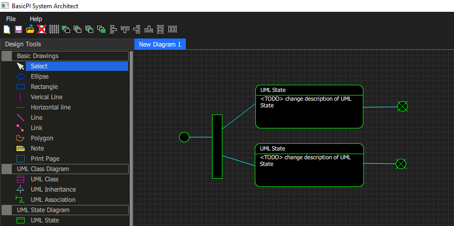
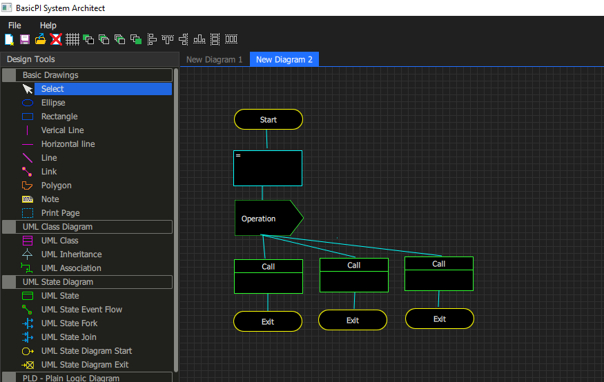
Qt/QML lack an image designer, but I found that using good, old MSPaint worked out well. I have added tools to support various modeling techniques, but will focus on HMI design and automation in this first version.

It is a graphical GUI designer included in Qt, but good luck getting something out of that. This is what I do not like with Qt – it’s a lot of stuff that simply don’t work very well.

The dialog above is what I get if I try to open my QML code in Designer – the code works well, but Qt Designer is not able to display it or offer a graphical design – and fiddling with graphical GUI design through text only is far to time consuming for my taste – so this is my answer to this – I create my own GUI designer because this is very straight forward.

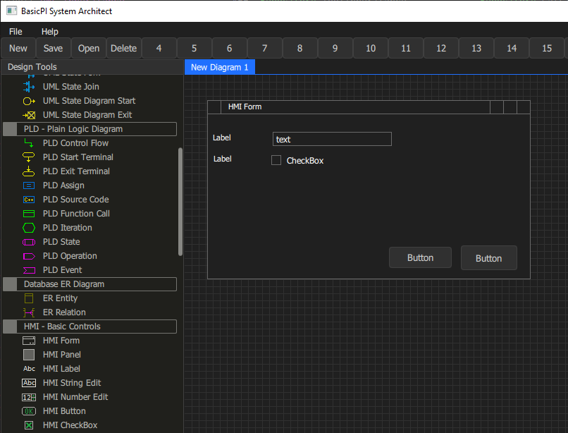
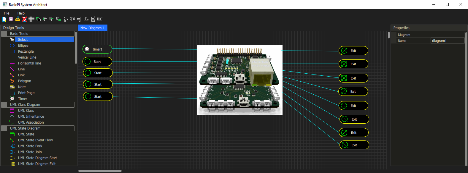
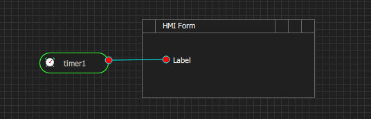
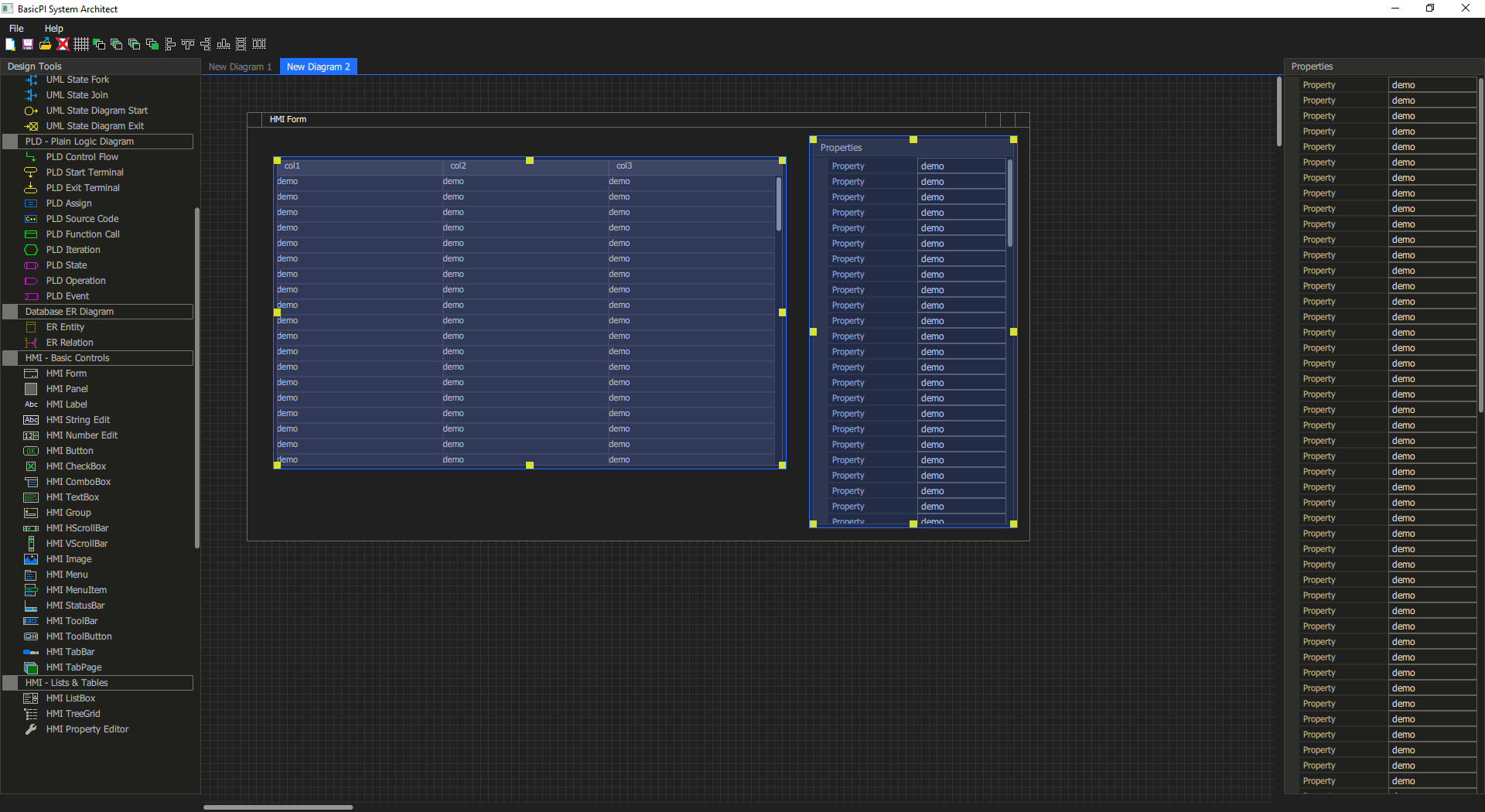
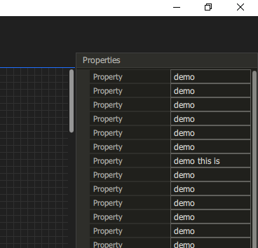
The reasons why I do this is because I need the graphical coordinates as input into an intelligent code generator so I can automate far more of the HMI application than I otherwise could. The core concept of the HMI designer should be very familiar – you simply draw objects on screen that look similar to the real GUI forms you want – this is just a drawing, but each object have parameters, a name and coordinates + property values I can use for automation.

Based on this I can auto-generate all QML and JavaScript as well as bindings to C++. Work that otherwise would take hours for every dialog can be done in minutes, but I will not stop there. Doing this for Qt/QML is just the start – I can as well do it for C# Core and others. My first target will be QML and I intend to create parts of BSA using BSA.

Auto generating an user interface is actually very easy, but the key is to accept a standard way of doing things that can be repeated. Take a simple edit field as an example – it needs to be initialized, you need to fetch the result and you need to validate the result dealing with wrong inputs – doing this properly is actually a bit of code that is repeated for every user control.

Those of you familiar with C# will know that Visual Studio generate a lot of code automatically to make C# Forms easy to work with – I intend to go further in the interest of dramatically increase productivity – or more exact – reduce the hours I need to use to create advanced HMI solutions.

I have started this designer in MFC, C#, Lazarus, classic Qt etc and it is doable in all of these, but I seriously wanted a technology that gave me easy access to GPU’s and this is where QML is unique. I plan gauges that is hard to do in old fashioned raster graphics because you start using to much CPU power, but they are straight forward in QML + not to mention that I actually can dig into 3D user interface objects.

Dark theme is sadly difficult to do – all the tools require that you either buy a package of controls or do the hard job yourself – QML is no exception. QtQuick controls out of the box have various quality and don’t look the way I want them to, so I ended up creating everything from scratch. But, QML makes that job very easy. I am seriously impressed about how easy it is to do graphic components. I will still be working on basic UI components for a while, but it is progressing fast compared to the hours I can put in.

Desktop-, Web- or Tablet- application? This is the advantage of a CASE tool – I do functional design and let my code generators deal with the rest. I see no reason why my desktop application should be different from my web applications or wise versa.

As mentioned – the first release will focus on GUI and QML because that is what I need the most myself. You might see a first, functional release before summer 2021.