![]()
Many solutions depend on something happening as a responce to time – it can be something you need to do 12 a clock Wednesday or every second, but to do so you need a timer object that can generate a signal on the requested time. This tool is needed in all diagrams in BSA for this purpose including HMI.
Assuming I want to read CPU Temperature from a device 10 times per sec – to do so I create a diagram with 3 objects – my device “device1”, a HMI screen with a label “label1” and a timer “timer1”. In the properties I configure timer1 to send a signal every 100ms. That signal is sent to device1 that as a response read CPU temperature and send this back. In the HMI device1.cpu_temperature is mapped to label1. Voila – we got ourself a temperature meter.
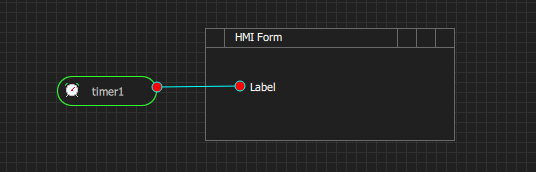
In the diagram above that is an actual BSA diagram you can see the solution. I have drawn timer1 and label1. In this case I used a Link Tool to create a line between them. The Link Tool is the base for many diagram line based links, but in this case it serves only as a comment to illustrate that timer1 is related to this label. Neither the timer or the link will be visible on the HMI. Timer symbol itself is formed as a start terminal/event that can be used in both PLD and UML State Diagrams.
A smarter solution would be to locate the timer on the device and only start/stop it from HMI to avoid extra trafic on the connection between HMI and device1. I will get back to how we join signals together later, but we basically declare device1 and specify how we communicate with device1 – once that is done the API for device1 will be available and can be mapped to objects in the HMI – no coding needed unless you want to.
A later version will allow you to visualize this in diagrams and do more than just passing events forth and back, but for that we either need to do some manual coding or UML/PLD active – fun for later.