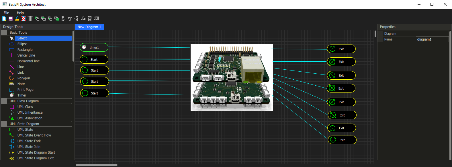
A “device” is a definition in our system that can be visualized as anything you want – in this example I use an image showing two of my cards attached.
What is important is that this device have input and output events – in this case shown as PLD terminals. This is a mock-up diagram (not real) so the actual diagram will have a few more details. Is this a UML State Diagram or PLD? Actually it is a UML State Diagram, but I can draw the same in PLD – and both are used the same way.
What the diagram show is that we have 1 timer and 4 input signals while we have 8 output signals. A signal in this context is a unique name with parameters. The device might have far more than this, but this is what I decided to import of the API in this case.
Part of the definition is that (1) I give the device a name, (2) I give info about connection protocol, (3) I define the signal list I am interested in. The rest is a black box.
Assuming this is a Modbus Device it will mean we need to import or create a Modbus table. Each signal is then mapped to one or more Modbus registers and the Timer will do the polling. As we set signals we just write to a local storage, wait for timer to do a write and read, and as we receive values we trigger the out signals we want.
This is just a mock-up/early illustration, so the actual diagram will be better. The HMI Designer will have a simplified version of this – we do not include the diagram only define the device as a component. The drawback is that any signal processing needs to be done in code, but that is where we start. As we add diagrams later we will be able to do processing a bit more visual as part of the diagram. But, we will still maintain the capability to just do this in code.
And how do we do it in code? Simple – pick up your favorite code editor and manually create a module that uses the BSA API. You can then import this as a “black box” with only the IO signal list available. and just use it.