DAB Radio Hat

I purchased the breakout board above from ebay earlier, but as I contact KeyStone Semiconductors I am told that these boards have custom programming and that they have no info about the firmware on this module, so be aware – don’t buy these on ebay.

I would like to use one of these modules to create a DAB Radio Hat. F405 have 2 x I2S channels that should match this board so we can digitalize the sound and send it back out to speakers or into Raspberry PI. That would make an awesome, programmable radio. The modules are 26x26mm and would fit perfect on a Hat, but it all depends on price and availability – so let’s see.

What can we use a DAB Radio Hat for? Obviously to create a Radio :), but having a Radio as part of a control system allows us to play radio channels that can be silenced and replaced with audible alarms as things happen, play Radio on timed schemes to give the illusion that someone is home or simply play radio multiple places in the house.

Connector Size

These 2.54 pitch spring terminals occupy more space than I hoped for, so I had to abandon current sensors on each DRV8313 to get room for them. The red areas are the spring connectors. The yellow is the MCU which I desperately need space around since I will be taking out close to every pin on this design.

I will add in a common current sensor. I also realized that for the current sensors to be of usage for 3-phase I need to mount it on a single PWM outputs (phase current). That array of 1206/1210 components are the capacitors. I decided to remove the larger one and replace them this an array to get the profile down.

Heat sink on this Hat is very straight forward – you mount it on the back to cool down the PCB. Notice that each DRV8313 have an array of holes connecting and venting out on the back side, so it is fully possible to mount this straight on a heat-sink.

Taking out 18 PWM signals on such a small design is maybe ambiguous, so I could drop down to 12 – 3 x 4-Phase, 3 x Steppers, 6 x DC Motors etc. If I did that I could move the MCU to right and attempt 12 (or 6) x current sensors.

The reason I keep on about current sensors is because they enable positioning on a 3-phase as well as torque calculations on both 3-phase and Steppers. With torque calculations on Stepper I could avoid end-stops on CNC machinery etc – simply detect where the end is and just put up a mechanical stop. To get more channels I can just stack up boards, so adding the sensors back is worth more than channel density + 12x 2.5A PWM channels are still a good. Hat.

Raspberry PI Hat’s

It’s been many Hat’s lately as I am focusing more and more on this as my main core for everything. I still have a load of Hat’s that I want to start on, but I won’t exactly have much spare time the coming year. This is just a summary of projects that I am working on and intend to complete.

XPortHub. Basically a communication Hub With CAN, RS485, RS232, SPI, I2C, USB + Micro SD Card, RTC, Flash etc. This Board is actually assembled and so far working well.

Wifi Hat based on ESP32 to enable a low-cost Wifi/Bluetooth With CAN, RS485 and a few IO ports. I have PCB for this Board, but have yet not assembled or tested it.
32 x IO / Servo Controller.

Not ordered.

8 x DC Motors + 16 x Sensors.
7 x 5-Wire Stepper Driver.
3KW Universal motor driver, Capable of 60V @50A on 3-Phase, DC, Stepper or Solenoids.
NB-IoT/4G Hat.
Light-weight 60V PSU. This is only a test board with the Hat format.
LoRa + GPS Hat. Shown With 12km 1W configuration.
LoRa + GPS Hat. Shown With 6.5km 0.1W configuration.
2A Motor Controller. Can run 6 x 3 Phase, 4 x Steppers, 9 x DC motors or 18 Solenoids/PWM signals. This is still work in progress.
3KW 3Phase Motor Controller. This uses DRV8301 and is designed for 60V@50A. This actually need a revision before it is ordered.
Mini stand-alone 3-Phase Controller for 2A. This is assembled and is working, but the 60V DC/DC needs a revision.
CAN – USB Adapter. Assembled in rev 1.1 and working.
ESP32 Utility Driver – 4 sensors, 8 Servo/IO, 2 H-Bridge, 7 PWM signals. This is assembled and working rev 1.1.
Model Train Cockpit Controller. This is a failure and need a revision + a support adapter. A rev 1.2 is on my list.
STM32FxxxRx Breakout Board. Assembled and tested for F105 and F405.
Breakout for STM32F031F4 or STM32F042F6. Assembled and working.
My SWD Adapter. This will need an upgrade, but it has been one of my most usefully designs. It enables me to use a small 1.27 pich footprint on my designs and deal With ST-Link 2.54 Pitch. Next Version will have Reset and Boot Connectors.
Micro sensors and actuators. I had 4 of these designs and the Temperature, Light, Proximity sensor will be upgraded. More external sensors will be added later.

And more – many of my older designs have either been ditched or evolved into more mature designs listed above. I will be focusing more and more on the new Raspberry Hat format for everything. The exception will mainly be a series of intelligent sensors evolving out of my STM32F031F4 micro designs.


2A Motor Hat – Connectors

Connectors on this board is a challenge because I want to support 3 different usages:

  • 3-Phase that require a 3 pin connector.
  • 4 wire stepper that require a 4 pin connector.
  • PWM that require 1 pin + ground for every signal.

The board above uses 2.54 pitch connectors with space to mount small screw terminals. The ones I show here is just an example with a 18 x PWM and 18 x GND connections. These screw terminals are good, but they require access from top – so an alternative is to use something like the ones below that are right angle.

These are 2.54 pitch – 2 rows with 5.08 pitch apart. A bit big for my taste, but I think I can support them. And they don’t rule out anything as 2.54 pitch is very flexible. Height is an issue because PCB separators are 13mm to fit headers – these are 11mm on the back and a bit taller on the bit that will stick out from the board – I thing they will fit well.I need to make a package and show a 3D with these on a bit later.

HMI TFT Candidates


This first TFT cost ca 3.- USD and is 0.96″ with 80×160 pixels, 64K colors and what seems like a Half Duplex SPI. What I am looking for in displays are high quality displays with bare-bone adapters only adding connector, PSU and mounting screws. This is the smallest candidate and will be a bit challenging as I can’t hide a Hat behind it. One rule is that the HMI solution can’t extend the panel size, so I need a cable option between this and the GPU board. The entire board is only 24x30mm so this is small.

This is the same display without the bare-bone adapter. One option is that I grab this and add this on the back of my own adapter with GPU, but I have so far avoided this type of connectors. The price difference is marginal. I will look into it.

This cost around 4.- USD and is 1.3″ with a resolution of 240×240 pixels.

I face the same option to either use the adapter or bare TFT on this one. The adapters are however so well done and makes my life so much easier that

The next is this 4″ display with 800×480 pixel resolution as I mentioned before. This uses a OTM8009A controller that is supported in STM32 and several variants exist for ca 20ich USD. They offer SPI or parallel Interface.

I seriously want a 7″ display with minimum 1024×600 pixels, but I have not found anything that that match my criteria yet. I have a 800×480 display for ca 40ich USD, but I expect more 1024×600 displays to pop up soon.

HMI Solution

The HMI solution I find most attractive is stand-alone TFT solutions with UART as interface. I have used a few off-the-shelf displays earlier and the concept is great, but I want to evolve this a bit beyon just a stand-alone TFT – I want a complete, plug & play solution.

These displays interface to embedded solutions using a UART. You pre-program the graphics in a GPU and use the UART to exchange data only. This is an excellent solution and concept, but I lack a few components.

  • Using a TFT for data input is not always convenient, I often need custom keys and knobs to make up the rest of a panel.
  • I don’t always want to pre-load the graphics design, I want an option to download graphics from the embedded system using XML alike formats.
  • I want to chose wherever I use Web, PC, Raspberry PI or something else based on my needs without having to program x number of HMI Interfaces.
  • Graphics quality must be high!
  • And at last, but not least – customization factor needs to be very high.

I have already started a HMI project with a HMI Designer for a Desktop, Raspberry PI, Android or iPad etc. This is still a bit work in progress, but what I want to add is the embedded “HMI Browser”.

This is just an example display – this is a barebone TFT with a dumb adapter that is perfect for my plans and it exist loads of these. I want more options than a single display, but this is a start. The base concept is that I stack a HMI adapter with the GPU behind this – and as the adapter will be a Hat I can add whatever I want to this again.

I will finish my 3Phase/PWM board first, but this is my next project. Completion of a HMI solution for my projects is long overdue!

3-Phase-/Stepper-/PWM-Hat

I have both 3-phase motors, stepper motors and PWM Hat on my list, so I want to use DRV8313 because this delivers 3 individual Half H-Bridges that are excellent for all of these options then combined together. I am pretty sure I can get 6 of these drivers on a Hat which would give:

  • 6 x 3-Phase Motors,
  • 4 x 4-wire Steppers, 
  • 9 x DC Motors, 
  • 18 x Solenoids/PWM signals. 
  • or any combination of these.

This would actually be a very powerfully Hat.

Looking at STM32F405RG I actually have 26 Timer pin’s with PWM capacity so this looks very doable. What I want to add in addition to DRV8313 is INA193 (or INA194) to measure current on each DRV8313. Ideally I would have this on every PWM, but I am running out of space here, so lets see where we land.

Getting 6 x DRV8313 on a Hat is very doable, but I will need a 60V DC/DC and 6 current sensors as well + a DC-Rail sensor – that is 38 extra passive Components. 

An early mock-up like the one above is just a quick exercise to place the actual components on the PCB for a reality check – and this does not look like a go to me. It is not just about placing components, but all the lanes I will need between them. And it is still capacitors etc that I would like to place here.

So what can I do?

Firstly – 60V is a bit ambiguous for this board, 36V (meaning 24V) is more workable meaning I can ditch the 60V/3.3V DC/DC. That helps a lot.

The second option is the filters that I have on the current sensors – I can remove these from electronics and do them in software – that will reduce 36 components to 12 and the density of the board is suddenly far more realistic – and less complex.

The capability to remove filters from electronics because I can do them in software is something I often face, and in this case we can due to the raw capacity of the M4 MCU. This last mock-up looks far more doable. And I am happy with a 24V limit on this board because this is for small 2-3A motors that seldom needs higher voltages. Now – lets og and design this one!

Smart SPI Schemes

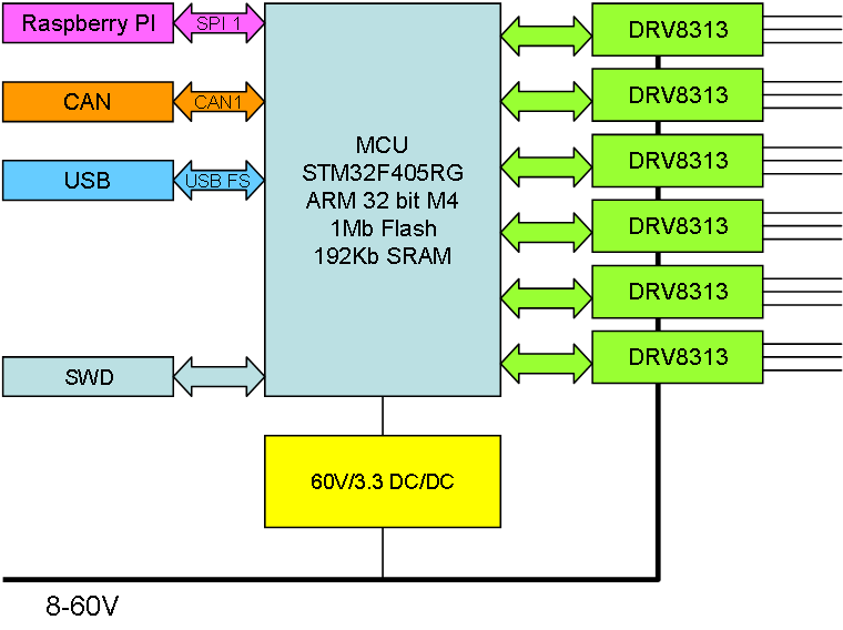
SPI is a very powerfully and fast serial port used between Master and one or more slaves, but I want to evolve the bus into a proper device to device bus. This is actually far more straight forward than I expected as both Raspberry PI and STM32F405 support Half-Duplex modes. RPI only support Half-Duplex Master, so all I need to do is to connect MISO and MOSI and set correct modes – Raspberry PI into Half Duplex Master and all STM32F405’s into Half-Duplex Slaves. Switching between sender is done in SW using a Dynamic time-slot scheme.

Doing this without Raspberry PI can be done in the same way by one of the devices taking over as Half-Duplex Master. The key here is that we have connected full SPI, MOSI to MOSI and MISO to MISO, but in Half Duplex one of them will be idle so we just connect them together. This should work!

F405 is capable of 42Mbps, but the closest RPI speed is 32Mbps – and if we assume 1ms switching time and max 4ms sending we should be around 25Mbps (80%) effective bandwidth usage.

This is a step down from 84Mbps bandwidth on a full duplex (F405), but it is still pretty good speed and very functional since we now communicate device to device directly.

The second scheme that I used before is using full duplex and using a dynamic time-slot scheme between device that send on MISO. This works very well, but I can only send to/from Master – never directly Device to Device in this scheme. This mode have the advantage of full duplex, meaning that with the same 32Mbps and 80% rule we have a 54Mbps total bandwidth. But, is this actually faster? The answer depends on your message flow – if all your traffic is to/from the Master then yes, if not we just waste bandwidth by turning messages around at master.

A 3rd Scheme of rotating Master is possible, but I fail to see what I would gain since changing Master means all communication goes through that device.

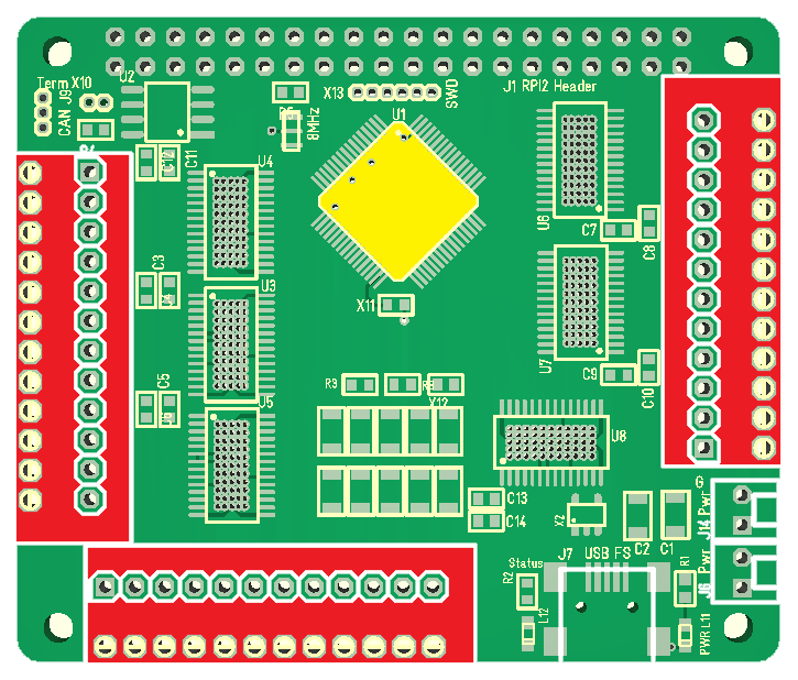
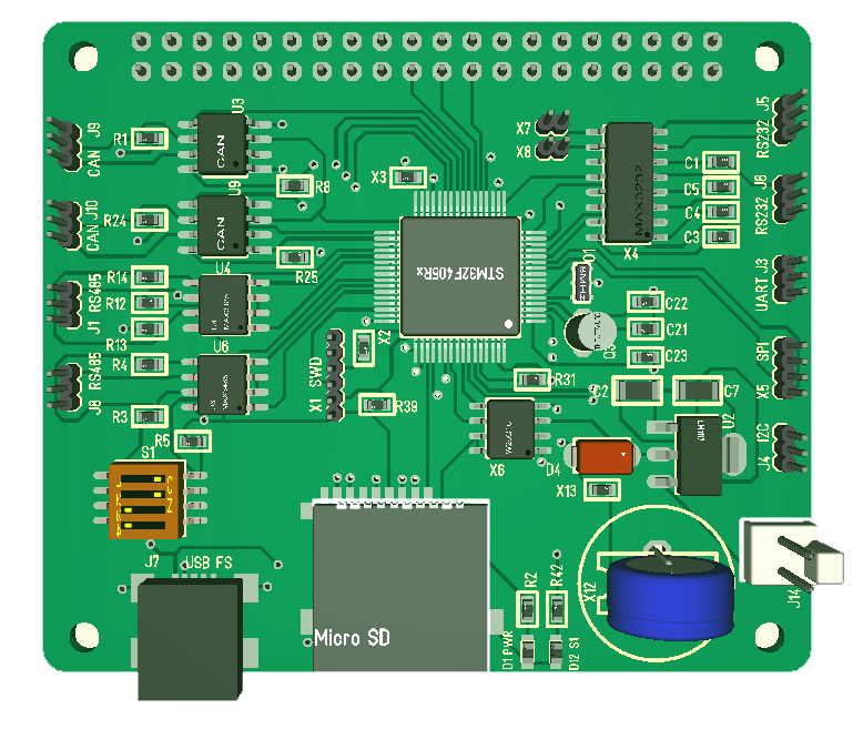
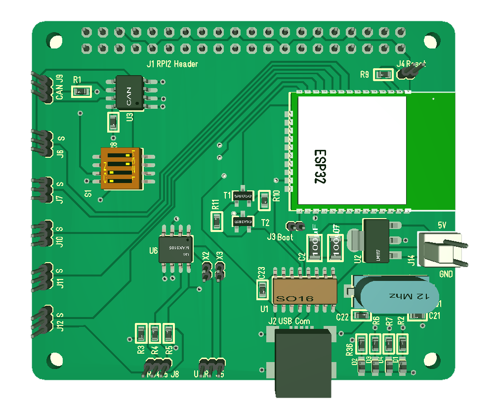
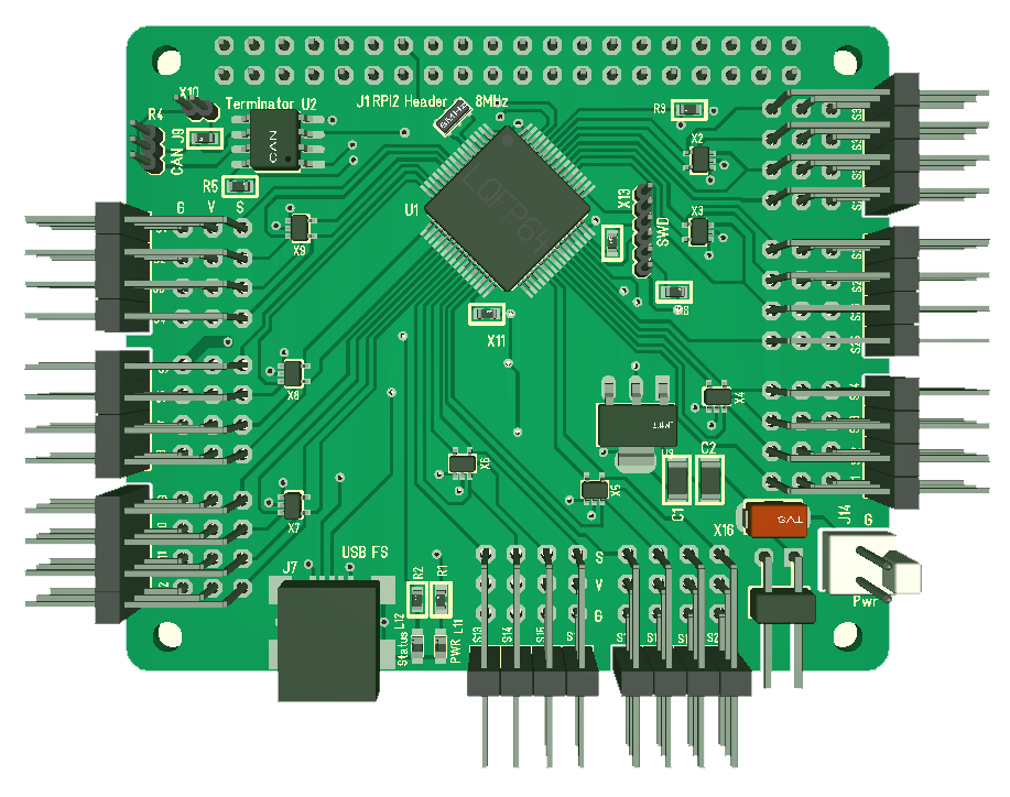
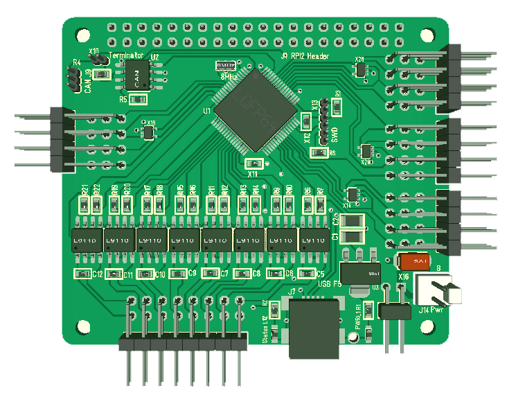
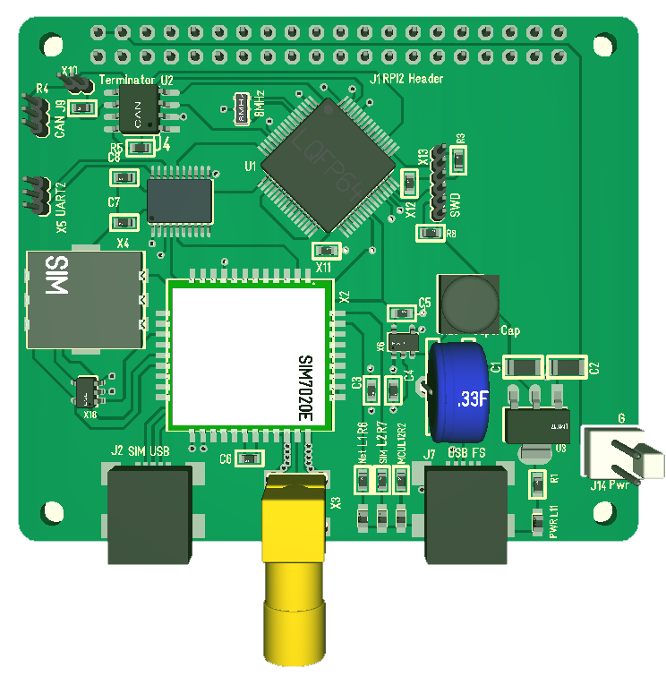
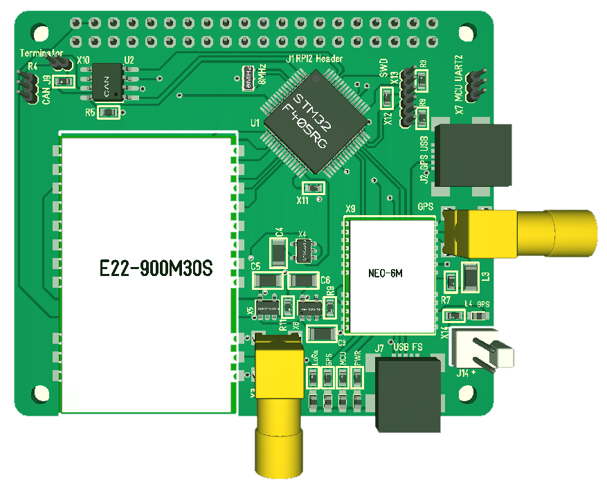
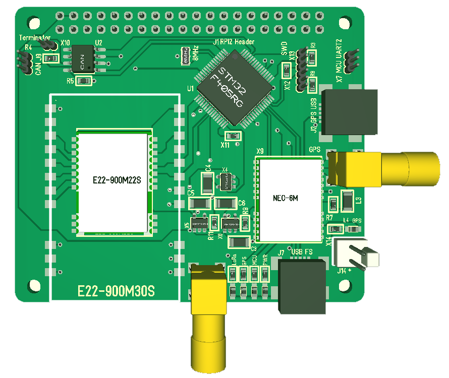
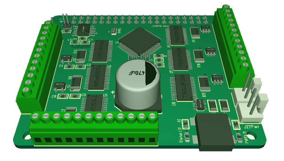
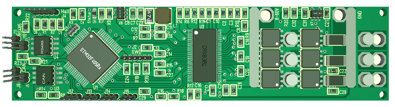
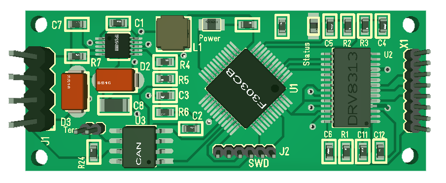
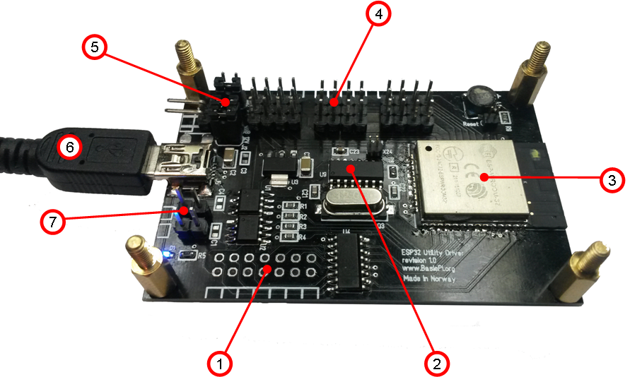
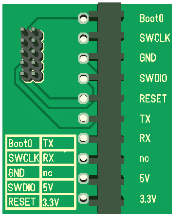
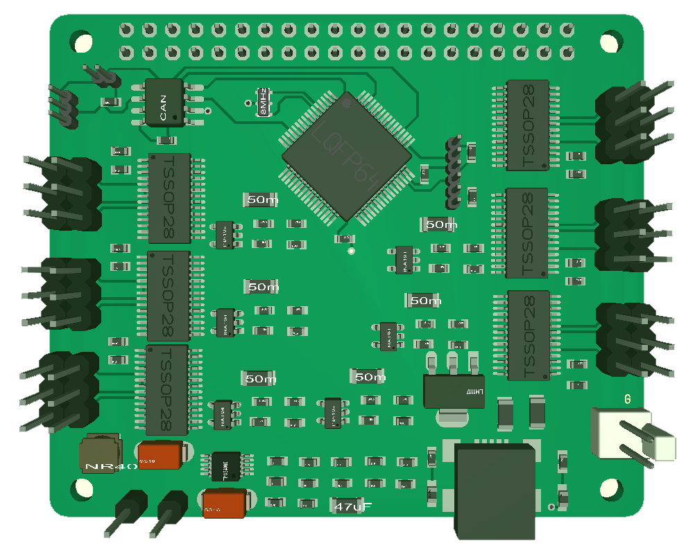
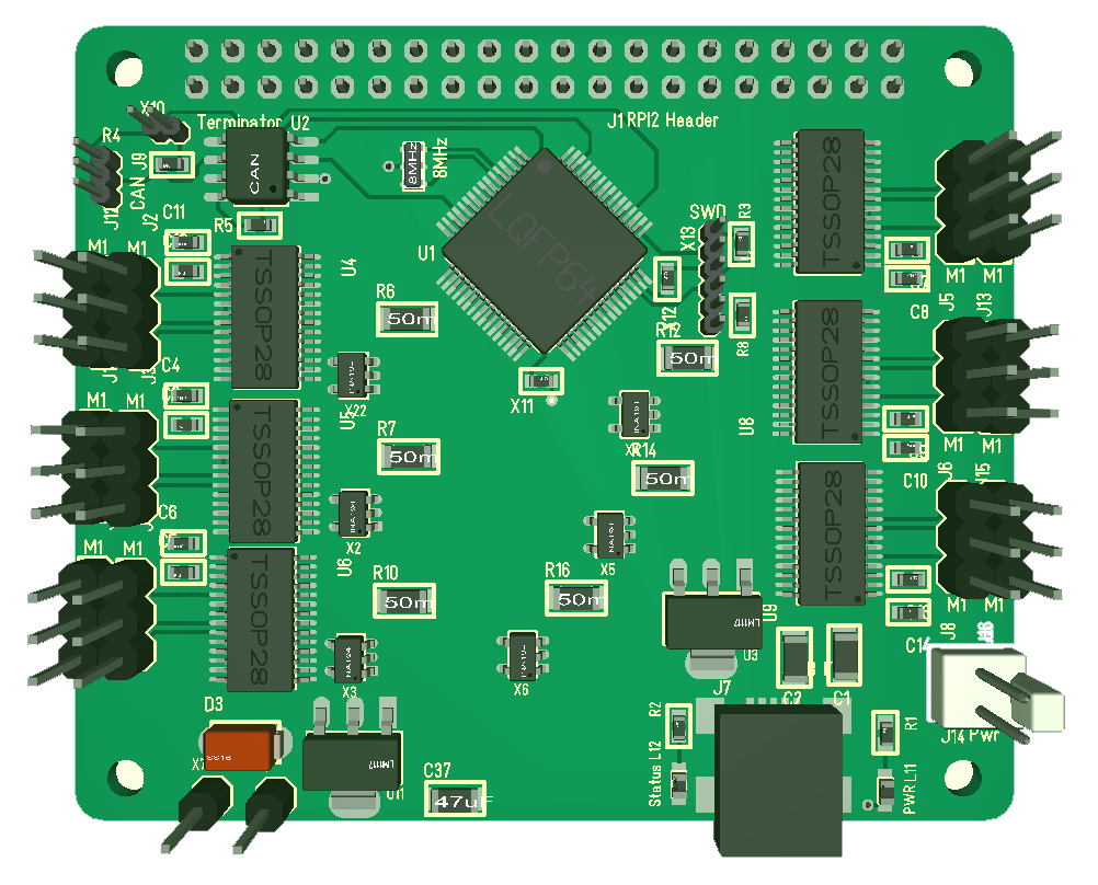
All my new Hat’s have full SPI connected and to enable Half-Duplex mode we simply add a jumper between MOSI and MISO on the header – this enables me to select communication scheme based on what I believe is most efficient.

Half-Duplex with STM32F405’s only will be at 42Mbps and as with ca 34Mbps effective bandwidth. We get lower speed with Raspberry PI because we need to fit available clock schemes with this as Half-Duplex Master.

Assuming we have 20 devices in a stack the max message wait time will be 5ms x 20 under full load which is 100ms. I am ok With that because this is a very worst case – I actually believe switch time is much much lower and we can improve parameters, but we can measure that later.

So how much bandwidth do we need for stereo sound? Assume that sound is 32 bit samples at 32Khz – this is 1Mbps bandwidth usage. This is a brute force calculation, but it still indicate that we have bandwidth for 25-50 channels of high quality sound. If I assume telecom quality which is 64Kbps we basically have capacity for ca 195 2-way phone calls simultaneously.

Doing video or sound over some distance is more of an issue, but don’t forget that we have Wired and Wireless Ethernet options as well.

To sum this up – I intend to abandon my attempt on rotating Master and focus on 2 schemes – Master with dynamic TDM slots on Slaves or Half-duplex with dynamic TDM slots that scale to load. I will be back with a more detailed protocol description later.

Upgraded LoRa Options

I finished the LoRa + GPS w/E22-900M30S earlier today and decided to add in E22-900M22S footprint. The modules are almost identical except in size. The only difference is that 30S have pin 10 to 3.3V while 22S have this to ground, so it is straight forward to have both footprints on the PCB.

The 3D model show the 22S module and illustrate well the size difference to the stronger 30S module. This enables 4 LoRa units:

  • E22-400M30S, 433Mhz, 1W, 12km range
  • E22-900M30S, 868Mhz, 1W, 12km range
  • E22-400M22S, 433Mhz, 0.1W, 6.5km range
  • E22-900M22S, 868Mhz, 0.1W, 6.5km range

All modules have an IPX antenna on the module, so I use a PCB antenna with wire to the IPX. This provides a PCB antenna option, but I can also use the IPX directly for more options.

As for the range listed above – this is datasheet numbers. It will be line of sight mostly and I expect somewhere between 2-6.5km for 22S. As for the stronger maybe 5-12km. I say this because E22 modules give very optimistic range data, but we will see.

LoRa/GPS Hat Annotated

  1. IPX Antenna for LoRa directly on the module.
  2. PCB Antenna for LoRa.
  3. Power leds + MCU Status.
  4. USB Connector for MCU.
  5. Separate Power connector.
  6. GPS Module. Can use NEO-6M, NEO-7M or NEO-8M.
  7. GPS Antenna.
  8. USB for GPS Module.
  9. UART TTL.
  10. SWD
  11. STM32F405RG. Powerfully ARM M4 capable of running MicroPython.
  12. Raspberry PI Connector.
  13. CAN Port.
  14. LoRa Module. 1W or 0.1W in 433/868Mhz area capable of up to 12km with up to 300kbps data-rate.

This board can function stand-alone, as part of a CAN stack or as a Raspberry PI Hat. LoRa and GPS can be switched off through separate power supplies.