60V DC/DC Hat

I decided to add the Hat form and RPI connection to my Hat allowing me to use this as a PSU as well. I need far more powerfully PSU’s than this, but TPS54260 can deliver 2.5A on any voltage I need, so it’s a beginning + its 3 voltages coming from this board so why not.

This is an easy change since it cost nothing extra. I could have made this board much, much smaller as well, but who cares. The purpose here is to test TPS54x60 circuits – the rest is freebies.

60V DC/DC Test Board

TPS54x60 is a very nice DC/DC converter covering up to 60V, but the circuit I used on the MC3X60V3A Motor Driver snapped at 30V+. I tested with 2 units before consulting a friend that suggested to add a 10uF capacitor very close to VIN. I have yet to test this because I did not want to sacrifice the one unit I had working. But, I need this 60V DC/DC working because I am using it elsewhere, so I decided to make a separate test PCB to Experiment with..

Reading the data-sheet for the TPS54160 I think my fiend might be right, but I am also curious about the EN pin. I left this floating which should be ok, but I need to test this. The last bit is the PWRGD pin which basically should drive a Led or something if power is ok.

Having a special breakout for this makes sense because this is a good circuit for experimenting with values for various voltages. For 24V I can as well do with a simpler linear regulator, but this is excellent for 48V. Yes it says 60V, but as I have explained before using a DC/DC converter at it’s limits with a motor controller involved is asking for trouble.

The next bits I want to add is 5V and 3.3V linear regulators fed from the 12-16V from the DC/DC.

The 3.3V have an enable that can be tied to VIN or driven by an external MCU pin. It also have a 0.33F Super Capacitor. This circuit should deliver 3.3V at 500mA.

The 5V circuit is identical, but do not use the Super Capacitor. I sometimes need 5V in addition to 12V and 3.3V, and the small SPX3819 deliver 0,5A from a SO23 packet making it an ideal small and low cost alternative.

The form factor of this board is a bit big, but the objective is only testing of the DC/DC so that is ok.

4G/NB-IoT Hat

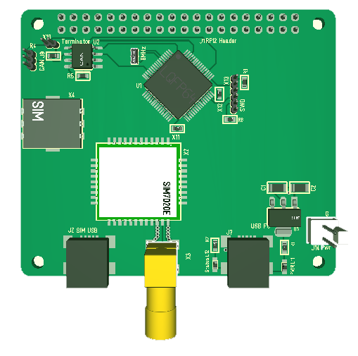
SIM7020E is a small module that offer 4G services and access to the new NB-IoT service that is available to give access to remote sensors that earlier was not possible. All-in-All this is just a new wrapping on a service that have been available since GSM and can be achieved with several low cost modules. The difference with NB-IoT is that is support better latency/cost schemes.

I really would have preferred to put 4G, GPS and LoRa on one Hat, but I will run into space and antenna issues so the 4G module will be on it’s own.

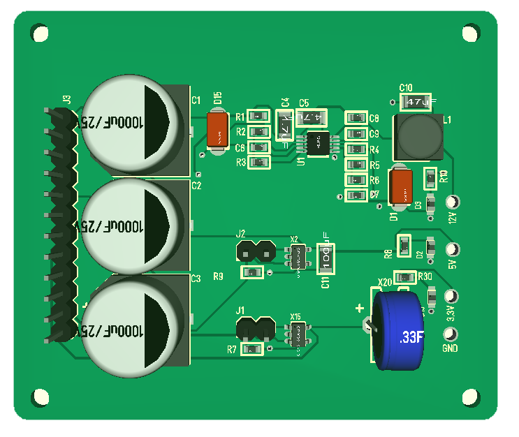
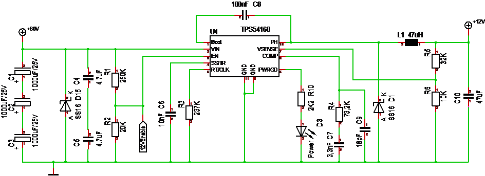
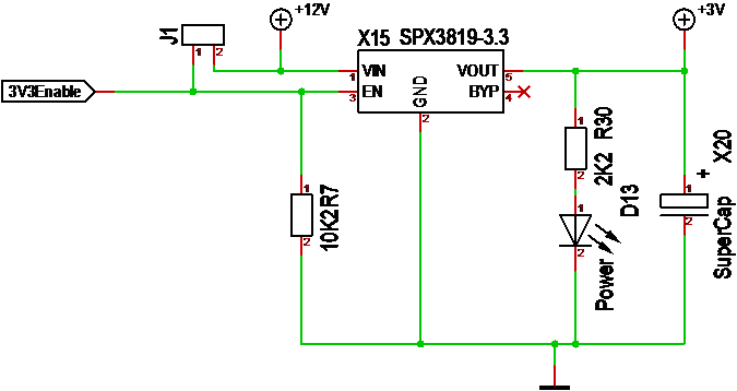
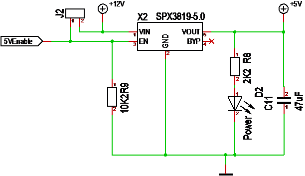
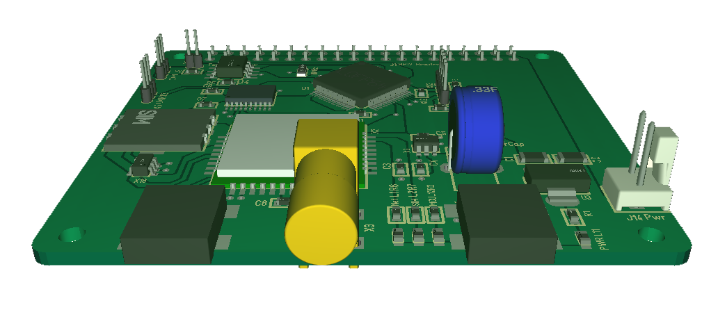
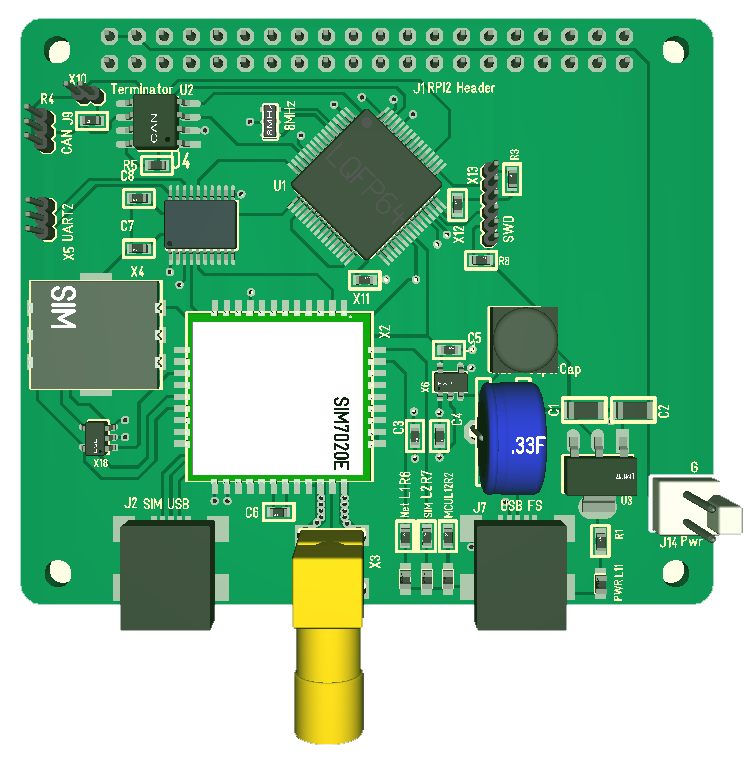
PSU requirement for SIM7020 is 500mA power peak, but this should be achievable through standard PSU. At some point I need to add a PSU module supporting my Hat’s, but that is for later concerns. To support the power and avoid a power dip I added space for a 0,33mF Supercap on the 3.3V. This should significantly reduce the peak current + the hole-though connectors can actually be used for a battery as well.

Debug is through USB or UART2, Firmware upgrade is only UART2 – a bit weird, but I have added both. Powering either of the USB’s will power everything to allow debug as needed with a single USB. ESD protection is added for VBAT (3V+, SIM card lines and UART2 lines.

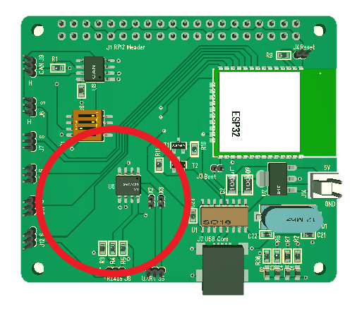
This is my 7th Hat in the new format. I had no reference on the SIM7020E schematics, so will be exiting to see if this works at all. Was a bit annoyed over the UART’s from SIM7020E because they where 1.8V, so had to add a level shifter. Used TBX0108 in SO20 format from Texas Instruments, so will see how that goes as well. Luckily I have a test board on the way so I get to test NB-IoT before I dig into my own board.

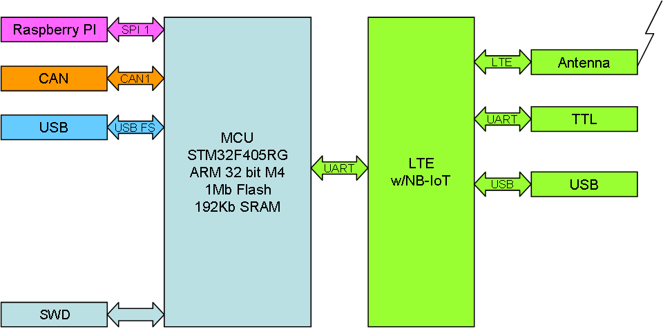
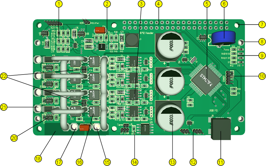
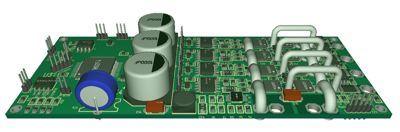
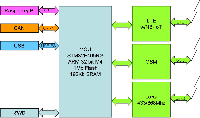
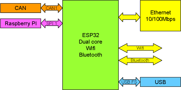
Functionality on NB-IoT uses a STM32F405RG to either connect on USB, SPI to Raspberry PI or CAN. Connection to SIM7020E is through UART on TTL level. Both UART’s are level shifted. The external UART is for Programming/Debug, while the extra USB also id for Debugging.

I have no experience using these modules, but I expect that I will be able to send/receive data using TCP/UDP at a speed of 26.15-68.5Kbps. It will be interesting to test.

Next out is GPS and LoRa Hat’s.

60V/50A Motor Annotated

  1. Hall sensor logic
  2. 60V DC/DC Converter
  3. Gate Drivers
  4. Raspberry PI Connector
  5. MCU
  6. SuperCap for 3,3V on MCU
  7. Raspberry PI mount holes
  8. Mount holes for heat-sink
  9. Leds
  10. SWD
  11. USB
  12. 2 x End point sensors
  13. PSU Capacitance
  14. CAN port
  15. +60V
  16. MOSFET Array
  17. GND
  18. Extra GND Connectors
  19. Current Sensors
  20. Phase output
  21. 2 x Temperature Sensors.

MC4X60V50A as a Hat

Updated 3D Model 18.dec.2018

This is a bit more than a mockup since it is almost complete, but adding 15mm to an existing design is a lot of extra space. I turned the Hat so that the Raspberry PI Ethernet would be at right. Basically this is 35mm wider than a normal Hat, so it is still small for a 3KW Motor Controller.

Actually I now have some extra space so I can add in a few things. I ditched a RS485, but I would also like more sensors if I have pins/space available. I have a connector to connect 5V on PI to 5V from Motor. This enables MCU and Driver to have separate PSU. I can also add pins to mount extra capacitors behind on the left side. This will be perfect as they will be left of Raspberry PI or other Hat’s. I actually could remove the large 1000uF capacitors on top to save some Space, but lets see how it works out.

Heavy Universal Motor Hat

This is an unfinished 3D of MC4X60V50A or MC4X for short. I initially stated that I did not want this as a Raspberry PI Hat, but I do have SPI1 available + CAN is already planned. It would make a powerfully module + I could add an isolated GW as an add-on etc. The controller itself is more or less finished and the driver stages are mature design.

Firstly I don’t need to attach a Raspberry PI, but it would be a very powerfully stack to be able to add the 20++ modules I now plan. If I add the 40-pin GPIO at bottom-left I would get the RJ45 and USB’s of Raspberry PI 2/3 at left as an extension. This could work out very well – lets try it out and see where we end up.

Just to remind everyone – this Motor Driver support 60V @50A. It basically does so on all 4 independent drivers, so you can run 4 x heavy PWM/Solenoids, 2 heavy DC Motors, a 3-Phase BLDC Motor or a heavy stepper Motor.


NB-IoT Hat – Mockup

This is an early mockup of a NB-IoT/4G/3G/2G/GSM Hat just to illustrate the space needs. My main concerns are signal quality on the antenna part as this module do not have a direct antenna output. Below is a PCB snap-shot showing the details of the antenna layout.

I really could have needed a 3rd layer here to completely isolate the antenna signal, but this has to do. The LoRa unit have antenna on the module so I can use a pre-made Antenna port air-with wire, but I will need to do something similar with the GPS.

SIM7020E also have a bigger brother with GPS in the module, so I will consider that as well. I have not sorted passive components and PSU yet – but, a 4G module is usually no wimp on sending, so I expect that much of the spare space I seem to have here will be used on special voltage PSU – not sure yet.

SIM808 that I used earlier is larger, cover only 3G, but it had GSM and PCM sound. The later is digital sound enabling voice services like IVR etc. The drawback with SIM808 was size and the need for 4V/3A as well as the 3G limitation.

The advantage of actual sound support is that we can make a remote doorbell unit directly connected with voice and video to your phone. I will however re-investigate that option using a different path because 300Kbps is actually sufficient for both a voice and video channel. Video will work with reduced frames per sec, but that is sufficient to see what is happening.

Radio/4G/GSM Hat

I drafted a GSM/GPS module some time ago, but I never ordered it as I decided to ditch that PLC design and pick up a smaller footprint. Time has changed so I want to make a new approach.

Using STM32F405RG as core I want to add NB-IoT, LoRa and GPS capabilities.

NB-IoT is a new 4G service allowing 300Kbps, low cost data links over mobile networks.

LoRa is Long Range radio and cover 433Mhz and 868Mhz modules to communicate up to 12 km with 300kbps speed.

GPS is as you know a system using satellites to detect position.

I want to make Raspberry PI Hat’s with these breakout’s. Looking into the practicalities I probably need 2 hat’s for this due to space restrictions. All three of these will need high frequency antennas, so I might for that reason alone need 3 Hat’s. Let’s see where we end up.

A natural infrastructure is that you use NB-IoT to reach remote places and then WiFi or LoRa locally. Both Wifi and LoRa units are secure these days. My real reasons for doing this has to be secret as I basically need these components for a test-bed/prototype and this is a great opportunity to add components to a modular Control system that is excellent for home automation and prototyping.


Ethernet/Wifi Hat

I want an Ethernet module to by list of boards. I can always use Raspberry PI 2/3, but I would still like to make my own as well. In the past I have used W5500 a few times, but this time I want to dig into ESP32.

ESP32 already have the TCP/IP stack, it has Wifi/Bluetooth and an Ethernet interface. A few vendors have also show schematics for Ethernet on ESP32, so it makes sense upgrading my ESP32 Hat with Ethernet. I do have the space if I drop the RS485 etc. A quick check also tell me that I have the pins as well.

The Raspberry PI Header can be sacrificed if I need to. CAN is the backbone bus and this is most attractive if I want to replace Raspberry PI as Wifi/Ethernet GW.

This Hat is not a priority, but I will make it at some point.

STM32F405RG Tester

One of the challenges I face is that batches with MCU’s from Asia are dodgy. This has been specially bad on STM32F405RG so I want to make myself a MCU tester for Rx and Cx series. I just tried to wire one and it kind-off works, but SWD wiring get to dodgy so I need to make a proper PCB.

I have one of these laying around and have ordered a few more, but I need to remove the breakout board and mount it on a dedicated test PCB.

  • Power and ground connected. Using a USB as power connector.
  • VCAP capacitors with switch so I can test both STM32F1 and STM32F4.
  • Led on all pins
  • Proper SWD connector – short cables. Rather than the 1.27 header I can use a 2.54 and plug ST-Ling/V2 straight on the board.
  • 8 or 16Mhz x-tal mounted.
  • UART1 connected on a connector so I can run a standard application and display some test IO.
  • Header rows for all pins.

It is so many functions on a STM32FxxxRx MCU that it is difficult to test them all, but the application above will get me airborne knowing that the MCU looks decent before I solder it on.

A STM32F405RG has a factory price of 5.8.- USD from ST and I would gladly pay that price, but before I receive a MCU from a distributor it cost me 17.- USD all included. So I use Asian sources. The challenge is that MCU factories also are in Asia and many people earn a few extra bucks by selling factory rejects. For prototyping many of these are “ok”, but then you have those that are not.

I faced the same issue with MOSFET’s earlier, but discovered that it was cheaper getting the MOSFET’s from Arrow so I had a bit of luck. Buying a STM32F405RG from Asia you get them down in 3.8.- USD these days. With a tester I can test them straight away and slam bad batches by claiming my money back and avoid the loss.

I will need to build the tester for each MCU, but I can probably sell of a few of these testers as well because I am not the only hobbyist or professional needing this and this type of equipment do cost money.

In fact, I can probably use 1-2 MCU’s to auto-test a 3rd MCU, but that us fun for later.