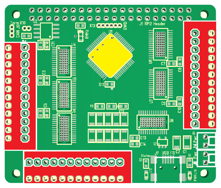
These 2.54 pitch spring terminals occupy more space than I hoped for, so I had to abandon current sensors on each DRV8313 to get room for them. The red areas are the spring connectors. The yellow is the MCU which I desperately need space around since I will be taking out close to every pin on this design.
I will add in a common current sensor. I also realized that for the current sensors to be of usage for 3-phase I need to mount it on a single PWM outputs (phase current). That array of 1206/1210 components are the capacitors. I decided to remove the larger one and replace them this an array to get the profile down.
Heat sink on this Hat is very straight forward – you mount it on the back to cool down the PCB. Notice that each DRV8313 have an array of holes connecting and venting out on the back side, so it is fully possible to mount this straight on a heat-sink.
Taking out 18 PWM signals on such a small design is maybe ambiguous, so I could drop down to 12 – 3 x 4-Phase, 3 x Steppers, 6 x DC Motors etc. If I did that I could move the MCU to right and attempt 12 (or 6) x current sensors.
The reason I keep on about current sensors is because they enable positioning on a 3-phase as well as torque calculations on both 3-phase and Steppers. With torque calculations on Stepper I could avoid end-stops on CNC machinery etc – simply detect where the end is and just put up a mechanical stop. To get more channels I can just stack up boards, so adding the sensors back is worth more than channel density + 12x 2.5A PWM channels are still a good. Hat.