Getting on with KiCAD

The graphical user interface on KiCAD is different than most applications. On KiCAD you get little feedback that you have selected something. Editing on PCB is quite “normal” – you select a component and click to move it. Doing the same on schematics are different, you select by using area and the component stick to cursor until you click again.

This is just one example of how KiCAD interface is a bit different than what you would expect from a standard Windows application. And this takes a bit of time to learn.

Comparing to Target 3001 it is a few things that are automated in Target and manual in KiCAD, but the rest is quite cool if you take the time to master the tools.

Target 3001 have multiple sheets with global labels, but KiCAD have a hierarchical sheet system. I basically use the first sheet for sub-sheet for every module in the system. But, here comes the main advantage – they are actual modules. KiCAD support local tags that can be used as interface if you re-use the component. This is a big advantage – I am about to redraw 32xServo/IO and can basically have one schematics referenced 32 times.

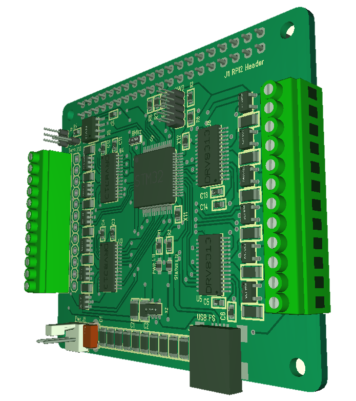
Integration between Schematics, PCB design and 3D View is close to fully integrated. It is separate applications, but you don’t notice that so much. What was most alien is that in KiCAD you draw schematics, afterwards you allocate footprints – so in other words you can easily change footprint without touching schematics. In Target 3001 symbol, footprint and 3D was always connected – it’s pros and cons on both – you just need to get used to the tool in front of you.

All in all I am quite impressed with KiCAD so far. Yes it takes a bit of time to learn, but many of the differences leads to more advanced tools that will help productivity. Using KiCAD without a community and dozens of videos would however have been very difficult.

Moving lines on schematics or PCB seems to be little automated, but it might be that I have not learned it properly yet. If I should compare Target 3001 and KiCAD I would state that Target 3001 is much easier to learn and master than any other tool I have tested so far. I do however feel that KiCAD will be better and faster to work with once you take the time to master it – and this is what matters because we are only newbies for a short time.

And lets not forget the most important feature in KiCAD – it is free. If I should continue with Target 3001 I would need to pay 1000.- USD for a fraction of what I got in KiCAD – which I can guarantee you is not an option. I have a friend using Cadence priced to something like 10,000.- USD per license and he brags about it a lot. But, I also remember a time then Embedded IDE’s JTAG’s and compilers costed thousands of dollars – I still pay license on Visual Studio at work, but even that is free for open source these days.

Burning lamp

Working with electronics you accept that it is a small risk of fire and take pre-cautions. But are we really prepared for what can go wrong? The issue is that everything around us contains more electronics and things that can take fire these days. Yesterday my lamp bought on Clas Olson took fire. Nothing bad happened, but the light tube took fire and wrecked the lamp. Changing light tube nothing happens, so this lamp is wrecked. Pictures below:

Obviously the fire started in the light tube itself, burned some of the heat resistant plastic and heated up quite a bit. I have never seen this happen before.

I was in the livingroom as it happened and came back to a dead lamp – no drama, but if something else had caught fire my house would have burned down. I am stunned to see that it is something inside the light tube that caught fire – probably the start device – I don’t know the proper name, but these types of lamps have a small “starter” that in this case seems to be inside the light tube itself.

The lamp is very nice for electronics work because it has a magnifier in the middle, so I have to replace this – or should I just upgrade it to a led lamp?

KiKad First Contact

I decided to make Rev 1.4 of the 32xServoIO using KiKad. One of many reasons for leaving Target 3001 and using KiKad is that I want to show more schematics out here. That has been difficult with Target 3001. The main reason is however cost – I use a free version of Target 3001 with some age and lack support for 4 layers etc. I will give you a summary of the experience once I know KiKad better.

One thing that can be said about KiKad is that it is much, much heavier to get started with than Target 3001. Things are different for sure – hopefully to the better once I get to know KiKad more.

What you see above is the bare minimum for ticking a STM32F405RG. In fact you can even drop the crystal if you don’t use USB.

And first point to KiKad – I actually can copy schematics out here now! I could before as well, but with some difficulty.

32xServo/IO Hat

These two 3D models show my old and new 32xIO. It’s a layout difference, but except for that they are mostly identical. The old board have the DIP selecting CS Pin for SPI, while the new dropped that.

Revison 1.1

Revision 1.3

The challenge with these 32xServo ports are that I do not have 32 PWM signals in HW. In theory STM32F405 do have 32 x PWM signals, but you can’t route them all at the same time. At most I get 28 signals if I switch everything else off – which I can’t.

The idea was to use a timer interrupt to bit-bang some of the pins to compensate, but to do that we need to actually use the MCU a bit. The classic RF pulse is 500uS to 1500 uS, so we need something like 50Khz interrupt or preferable 100Khz interrupt to process with some accuracy. I would have preferred using PWM signals only, but that is not possible. Also, we do actually have a powerfully M4 ticking at 168Mhz to support this, so we have plenty of juice – we can do this. The test is to put signals on a Servo and watch their behavior as they hold selected positions. I tried that with SW on a ESP32 and noticed “twitching” – small movements before I switched to HW PWM channels.

The way it is routed on 2.3 means I have:

  • 32 x GPIO channels since all are GPIO.
  • 17 x 5V compatible GPIO channels
  • 15 x ADC channels
  • 22 x Hardware PWM Channels.
  • 1 x SPI port for backbone bus
  • 1 x CAN port
  • 1 x USB port
  • 1 x User Led

I do however notice that I can optimize this a bit:

  1. I have used PC1 which is ADC capable for Status Led, while I have PC13,14 and 15 that are GPIO only available. This gives me one extra ADC channel, meaning I get all 16 ADC channels on IO.
  2. PC13, PC14 and PC15 can be used for Led’s giving me 3 user leds.
  3. PB12 and PB13 can be used on CAN2 releasing PB9 and PB8 from CAN1. That gives me 2 extra PWM/GPIO channels replacing 2 x GPIO only channels. CAN2 is Slave only thought, but I think I can accept that.
  4. If I ditch SPI1_MOSI and accept that this board only can be used as Half-Duplex Slave will free a PWM capable pin. I have to think about this one.
  5. In addition I need to add resistor options on SPI as well as the new SWD connector.
  6. Replace 2.54 pitch jumper with a 1.27 pitch.
  7. Move + Power lane away from ground plane looks doable to get a better ground plane.
  8. Move USB connector to right side closer to PSU.
  9. I also need to evaluate capacitance on the power connector.
  10. That leaves one change – I need different PSU on the 16 first versus the 16 last. Or more correctly. I think the solution here is to add an option to select between 3.3V/5V or Servo PSU on the 16 ADC capable channels.

I guess I can as well just start re-wiring this PCB from scratch due to the number of pin changes. But, I think this will be worth it + it is not that much work once I set my mind to do it. It is actually far more work making SW, but again – the changes will only affect the “wire” function and capability list. Done right Rev 1.4 should have:

  • 16 ADC/GPIO w/Mixed HW/SW PWM to left
  • 16 GPIO w/ HW PWM to right

PWM12 rev. 1.3 Draft

Started to make a few modifications on PWM12 Rev 1.3. replaced spring terminals with 2.54 pitch screw terminals. Discovered that if I mount them on the edge I can access the screws. And I did not like the spring terminals at all. Also removed the 5V connector and added SPI resistors.

PWM Abstraction Layer

Designing a PWM Interface is easy, but using ST’s “HAL” layer requires a bit of testing. A friend of mine decided to write his own drivers because he believe ST’s drivers are over-complicated and too low level. I agree, but I prefer to make my own C++ Abstraction Layer on top of the drivers.

So how should a PWM Interface look like?

Using PWM we have one limitation. One timer control many PWM ports. The example below is from STM32F405RG

  • TIM1 4 PWM signals
  • TIM2 4 PWM signals
  • TIM3 4 PWM signals
  • TIM4 4 PWM signals
  • TIM5 4 PWM signals
  • TIM8 4 PWM signals
  • TIM9 2 PWM signals
  • TIM10 1 PWM signal
  • TIM11 1 PWM signal
  • TIM12 2 PWM signals
  • TIM13 1 PWM signal
  • TIM14 1 PWM signal

In total 32 PWM signals, but TIM1 as an example control 4 ports and those 4 signals must share the same frequency, but they have individual duty cycle. Channel 1–3 on Timer 1,2,3 and 8 are used in PWM12.

  1. – start/stop each channel.
  2. – Frequency configuration of timer in Hz. To make this simple I also add frequency on each channel knowing that if I configure channel 1,2 or 3 to different frequency I will change all 3 channels.
  3. – Duty Cycle in %
  4. – Manual On/Off. On is 100% Duty Cycle while Off is 0% Duty cycle.

Wiring of PWM signals are the same as others. The same signal can be wired to different ports, so we wire each PWM signal to a Timer and Pin. This should be done in application initialization and is the only place where source code need to deal with physical layout.

This will work well for individual signals, but I also need to cover 3-Phase Motors, DC-Motors and Stepper motors in the Abstraction Layer as well as dual frequency signals.

A dual frequency means we pulse with a selected frequency and duty cycle and then use a secondary timer to create a lower pulse frequency based on that. This is an excellent way of providing PWM with an “amplitude”.

A 3-phase signal will use 3 or 6 PWM signals on a selected frequency – lets say 20Khz and then change duty cycle for each signal. If we use 64Khz we might want to change duty cycle only at 10Khz to avoid over-running the MCU as we need to do heavy math for each change.

DC is simpler as we use 2 signals and a selected frequency using duty cycle as speed (amplitude).

A stepper is even simpler as we use a trapezoidal algorithm to set position step by step. But, we can use the same trick with a higher frequency pulse to simulate amplitude and control torque.

This gives me the following AL classes:

  • alPWM – single PWM signal
  • alDCM – DC Motor composed of 2 PWM signals
  • al3PM – 3-Phase motor composed of 3-6 PWM signals.
  • alSTM – Stepper motor composed of 4 PWM signals.

In addition to the PWM side of things each class also need functionality to control it’s motor algorithm, but I leave that for a later entry.

DRV8313 Bug Found

This puzled me because the 4 circuits on PWM12 was copied from the working motor controller, but looking at the schematics I suddenly realized that 3.3V out from the buck converter is connected to ground – which explains why I draw 10mA++ extra current and why the internal logic don’t respond – it was shorted. I actually have the same bug on the motor controller as well, but I have obviously fixed it there and forgotten to take a note – bummer!

I looked at various schematics using DRV8313 to make it simple and must have picked up this bug. I don’t use 3.3V from DRV8313 because it is to little, so all I needed to do wss to cut 3.3V loose from ground and things should work as expected. The 3.3V on DRV8313 actually annoy me – it is only 10mA – unusable for most things.

As I said – something utterly simple and stupid, staring me in the face and duplicated on all 4 circuits – doh.

Trapzoidal w/DRV8313

This screen shot is from MC3X60V3A that also uses DRV8313. I fired it up and looked at code because I need a reference as I try to understand the errors I have on the PWM12 board. I use the same circuit, so I am puzled.

Trapsoidal algorith is a 6 step brute force algorithm where you control speed by frequency of the steps. It is easy to code and a quick test to verify drivers & motors.

Problems with DRV8313 on PWM12

I have used DRV8313 in a project before and it worked well, but on my PWM12 Hat I seem to have 2 busted chips so far. I selected both from the same batch, so I will add a 3rd from a different batch and see if it works.

PWM12 is a very simple Hat and DRV8313 is straight forward to use. I will not know the answer to this before I get a circuit working, but I suspect a bad batch again. One indication is that the two I have used so far behave differently. The first output ca 1.75V, while the other output 0.

It is a reminder that I should stop buying advanced chips from Asia on aliexpress. Luckily I have 4 different batches, and I don’t know if this is the cause yet.


Update 1: Adding the 3rd circuit I get the same output as from #2. #1 have an offset the others do not have. What puzle me is that I have absolutely no signal from any of the DRV8313 chips and this was 2 different batches. I can measure input voltage, I can measure that nRESET, nSLEEP and EM4 signals are correct. I can also see the pulse – that shoul be it – I should see an amplified pulse on output. You see the schematics for the circuit #4 above – it is seriously not much to this.

I also notice that I draw ca 70mA with 3 x DRV8313 connected regardless of what signals I give. It is almost as if I have done a systematic or common error on all 4 circuits. Luckily I have a different motor controller (MC3X3A) that uses the same chip and is working, so I need to use this as a reference. In absolute worst case I will re-solder a verified, working DRV8313 over to a PWM12 board.


Update 2:I have added the 4th circuit from yet another batch with the same problem. I see an unusual power usage – ca 25mA (ca 6mA on the one that works) and no response. All signals in are ok – Power, ground, Enable, Reset, Sleep and PWM. My next step is to solder up a motor controller and using a DRV8313 there for so to move it to a PWM12 Hat. In addition just let the problem rest a bit and look at it with fresh eyes one of the following days. I suspect that I have done something blunt stupid and simple, but I can’t find it – yet.


Update 3: I moved a DRV8313 that was not working on PWM12 over to the motor controller and it works perfectly! Meaning it is something with my schematics or PCB layout that is off on all 4 circuits. In one way that is a relief because it means my batches are good – at least some of them. Now I just need to figure out what is wrong on PWM12.