
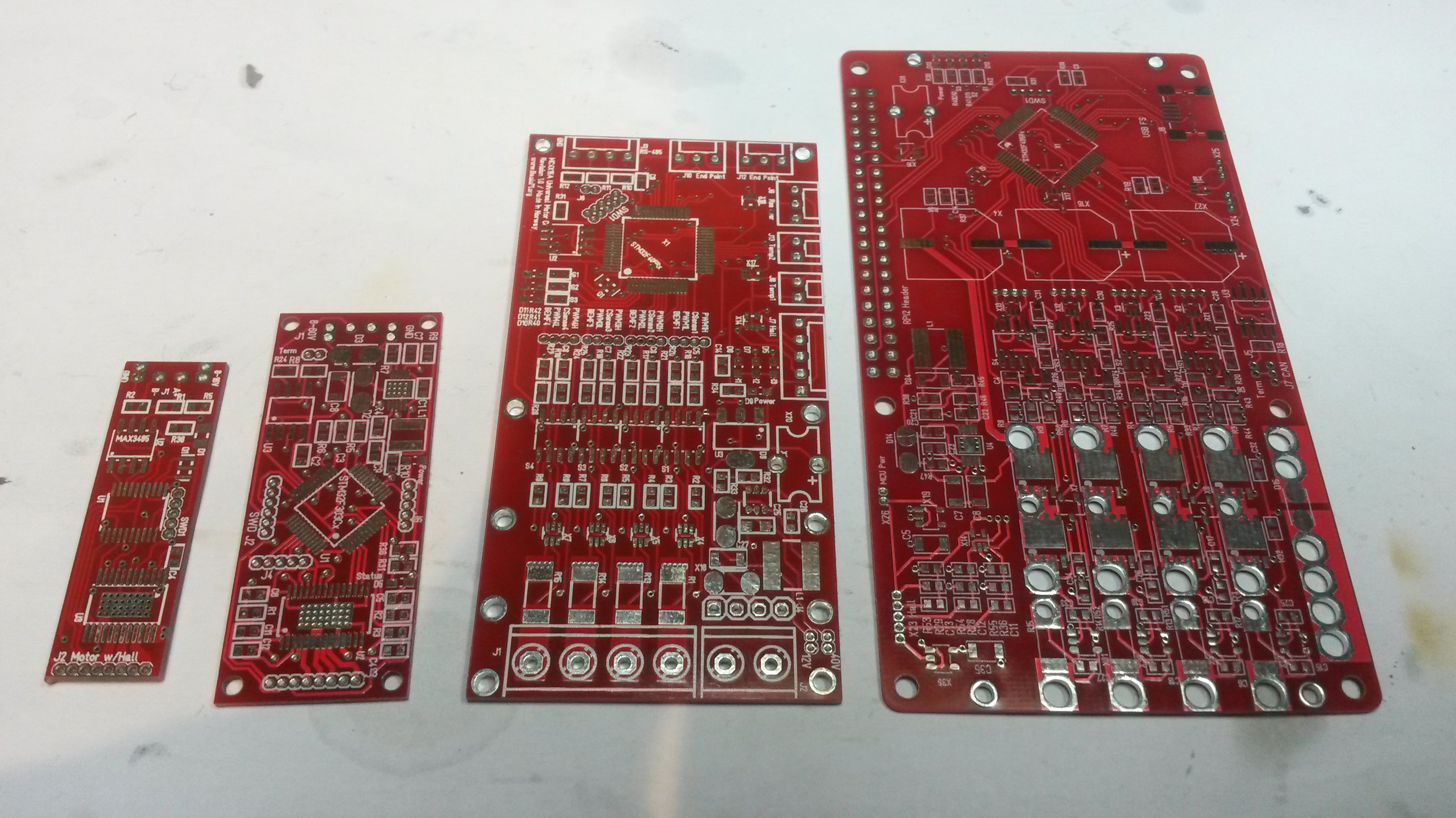
This is an awesome design allowing 60V @50A on 4 separate Half H-bridges. The design is a step up from the 30V/20A design using more powerfully MOSFET’s and adding wiring to support higher currents. It is also a Hat design, meaning I can add Hat’s to extend the controller. The pic above show my specialized motor controller PCB’s with this one at right.
I face some practical challenges testing this. Some of you might recall that I had challenges with 20A – I simply had no PSU that could support it. Or well – I actually do now. I do have a 60V/20 PSU and plan to build 2 of these.
My main concern and maybe biggest mistake is however the design of the air wires. I have 2mm wires, but lack the 3mm and realize that the way I have designed the 3mm makes them very difficult to create and solder on. This is a design with components on a single side intended to make it optional for production, but those wires require a lot of manual work defeating the object.
What I lack on this is a galvanic isolated communication interface. I attempted one earlier, and it worked, but heat dissipation was larger than I wanted. So what I will do is to create a separate Hat for this purpose later.
I should also point out that I might separate this board into 2 boards. One Driver and One controller. The interface between the MCU and MOSFET driver is more or less standard and I could need a galvanic interface here as well which would be easier to add if I separated the boards + it would allow me to add even more powerfully drivers.
The 4 separate channels means I can drive 4 solenoids, 2 DC motors, a 3-phase motor, a stepper motor or any combination. It is 4 x High side current sensors, hall sensors, CAN interface and USB. MCU can be powered by USB to keep it separate.