BSA – New Gauge

Just playing around with a Torque Tool Gauge. Bit work in progress, but using a wide band as needle rather than a classic needle and due to how my gauges are build up I can easely get them adapted to various stiles. This provides 4 gauges at the space of one – a bit work in progress – playing with ideas.

I made a huge amount of components in BSA, but decided that I needed the components as a stand-alone library and be using them manually in C# before I let BSA generate code and use them in applications. Building a Gauge library is fun.

PnP with Tank Belts

I finally got the two tank belts designed and added to the frame – so will get around to mount the plates and wire the machine. The tank belt at right hang a little so I will mount a holder to lift it up a bit, but otherwise I am good to go. My current “lab” is an old bed-room, so I need to clear the proper lab in the basement again before I start designing the cabinet for the machine.

I find designing with FreeCAD very easy once I got into it – very funny to design and print your own components. The picture don’t show the holders very well, but it is basically just boxes with screw holes ready printed using PETG plastic.

PnP – Head/FreeCAD

Finally got around to design holders for my Nema8 Nozzle head + I added a damper between the Nema17 and the head to reduce noise. I need to design tank-belt holders and I can start assembling pneumatic tubes and control system as I should have all parts by now.

I used FreeCAD to design these brackets. FreeCAD works, but it is a lot of bugs so you need some patience to use that in it’s current stage (version 0.20.2) – but, I am looking forward to new versions of FreeCAD + I need to learn more about it.

One of the things I want to do is to redesign the PnP Head completely. I work with Robotics as a profession and while this design is working I also see a lot of potential for mechanical improvements. As mentioned before I want to achieve 0201 quality and to do so I need to improve the mechanical accuracy/stability of the design. The white components above is PLA, while the black is PETG – a stronger type of plastic – but in the next design I want to avoid plastic on critical parts that will wear with movements. This is a machine with moving parts – it need to move fast and with some strength. The plastic design will work fine for a short period before it starts to wear out and not to mention that it will need constant adjustments. But, this is things you learn as you build one of these.

I also want a head with 4-8 nozzle tips on + I am very sceptical to the belt driven mechanism above – I suspect it will strugle with changing nozzle tips because you need some strength to click the on/off, but lets see. I will upload the changes I do to this machine, but contact me if you want them now.

I did notice that someone had dropped the adapter (in white) on top and made a non-turnable adapter – I will advice against that – that is 40.- USD that you do not want to save as the Nema8 will twist the pneumatic tubes and cause them to wear out fast.

Also remember that the z-gantry needs oiling from time to time.

The drawing above illustrate the current frame design with 4 x 2020 aluminum profiles (V type). I considered going up to 3030 or 2040 etc, but I do not have an issue with the strength of the profiles – I do hoverer have an issue with the entire frame moving a bit. So what I want to do is to double the width of the frame as follows:

This will increase the Y gantry to 1200 mm and stabilize the frame at the same time. To do so I only need to buy 3 x 2020 profiles that is 1200 mm long + 1 extra 600mm profile. I think this will do more for stability than adding larger profiles. Using the extra sis is an issue because I seldom need feeders – as most hobbyists I use strips and components in trays – I need the extra space to put this on and this is a low cost and very effective modification I think.

PnP – Attention to details

I ordered CNC belt driver wheels a bit quick and realized just now that their hold is 6mm while the shafts on my steppers are 5mm. The extra 1mm meakes a “hump” as the belt move and the combination is not a nice, smooth belt drive – so new belt wheels have been ordered. I am still waiting on tubes anyway so it will be february before the PnP is running. But, ordering parts from AliExpress used to be 8 weeks while it now is more like 2-4 weeks. Things have improved. I have to pay tax on everything, but all this is nicely organized from AliExpress. That said – some parts are cheaper on the local hardware shop.

BSA – Save/Load

As mentioned before it is easier to blog about HW than SW, more to show. But, that is about to change because BSA is very visual once it runs. The screen below is just a demo/test for Save/Load functionality and once that is working I can easier blog actual about diagrams. I must admit it was nice having a short break from BSA because this project have lastet 1,5 years now and it is a lot left todo. But, I do hope I can have a consistent demo that you can download sometime in early 2023.

1-2 days more and Save/Load should be working, meaning I can start on an example code generator next. The way to test save/load is to create something, save it and then load it to see if it is loaded. And then I save it again on a different file and compare files. I also add a lot of integrity testing as I load – in case of any error I decline to load with an error message. The saved file is XML alike so the user can edit it manually.

In the future I will add JSON format as well, but XML was easier for nw since I had a tailored parser already.

Happy x-mas and a happy new year!

PnP – Noozle Head

This picture (above) show the PnP Nozzle head. (1) A Nuki 506 Noozle, but I have several noozles. (2) A noozle holder. (3) A Nema8 hallow shaft Stepper and (4) And adapter for rotating hallow shaft to vacum tube. These are some of the most expensive parts of the PnP design. I have received 501 Nozzle that is designed for 0201 components, so we will see how far off we are in mechanical accuracy.

This picture is the entire Z gantry lacking belt and camera. I had to repair one of the adjustment bolts as it did not hold and you don’t need much insight into mechanics to understand that this would be better as metal parts. But, they cost me ca 10.- USD and 30 hours in printing, so they will have to do as a start.

I have 3 cameraes and multiple lenses. I initially assumed that an expensive, high resolution camera would be better, but recommendation is to use 720P cameraes. The algorithm only focus on recognizing position and some parts and higher resolution will make the machine slower (need more time to compute).

These 3-Way peunmatic solenoids was cheap, so I ordered a 6V and a 12V. The 12V is the right size for the job and tubes. These are both small and cheap.

PnP/PLC – Control System

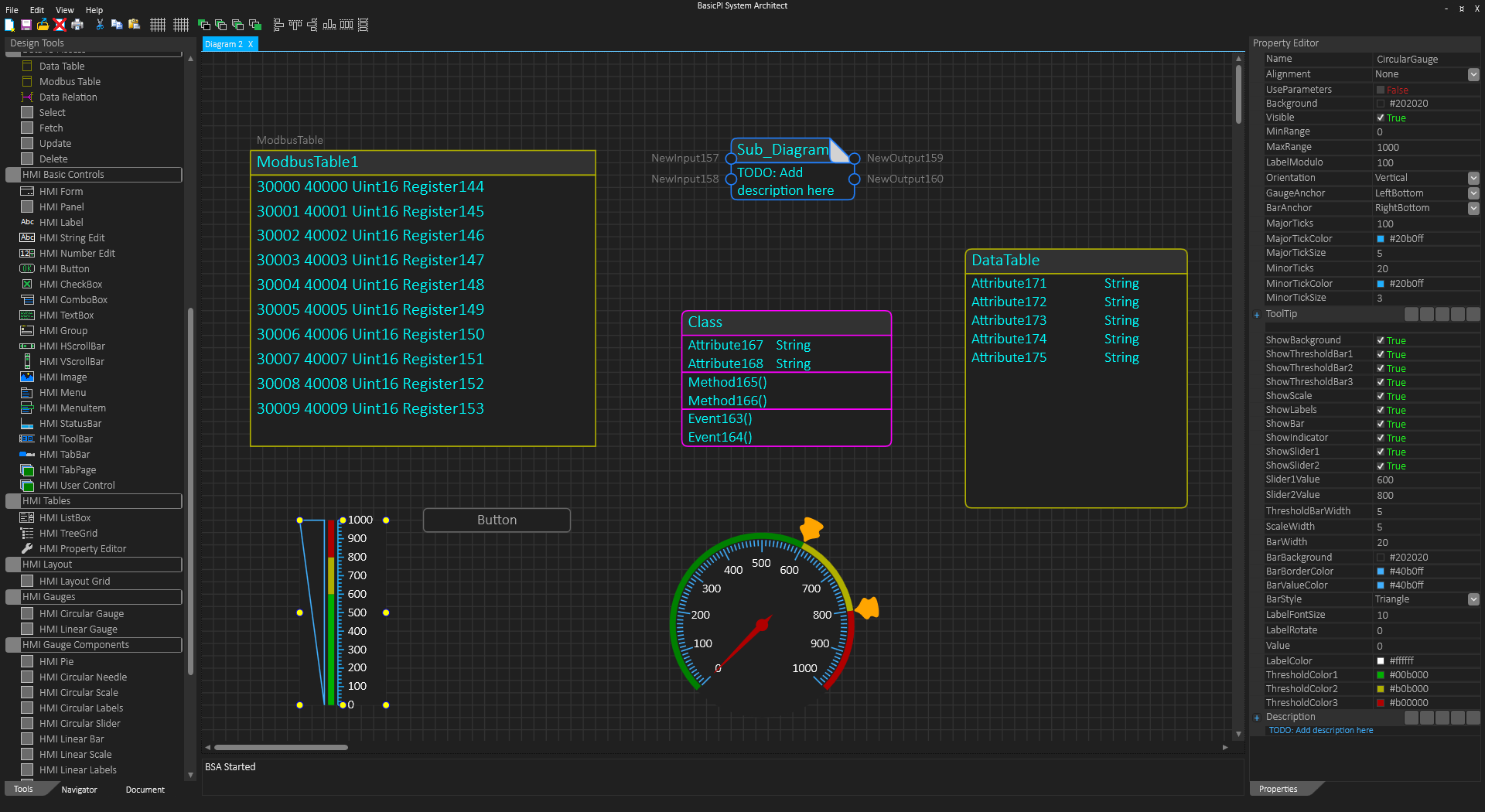
This is an early draft of a new, scalable control system for the PnP and later CNC machines. It is based on my own PLC system. I will re-use an older 3D Print control system or even get a OpenPnP control system in the first place, but I want to replace it with my own a bit down the road simply because of scalability and because this is an excellent test case. Using a modular PLC will in most cases never compete with a all-in-one control system in cost, but it offers doers an option to plug & play and make their own systems without digging into complex electronics and firmware as part of the prototyping.

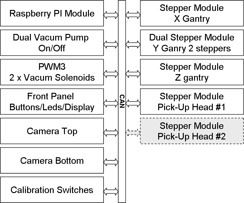
CAN is a much better IPC than RS485 on machinery because you can have multiple nodes that communicate simultaneously as one system. The design here is to use a Raspberry PI with Displays, Keyboard and Mouse as a top-side for the PnP. The Raspberry PI Module will interface Raspberry PI to the internal CAN.

As for Vacum Pump I plan to re-use the more expensive unit I have so the only interface here is a relay switching 230V mains on/off. I have the alternative cheaper pumps as well.

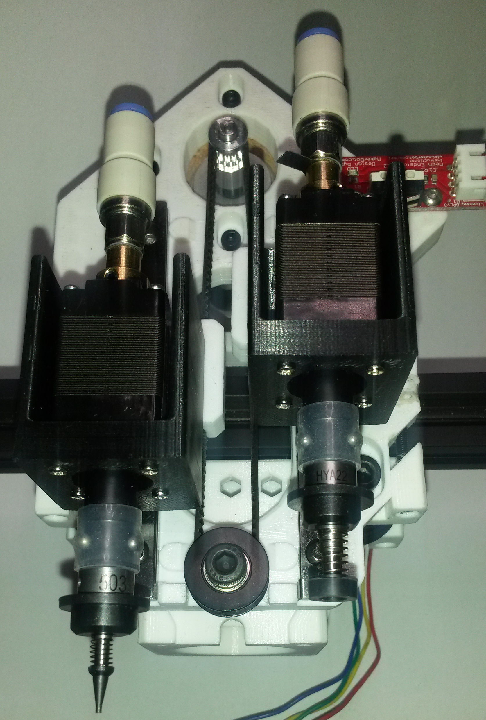
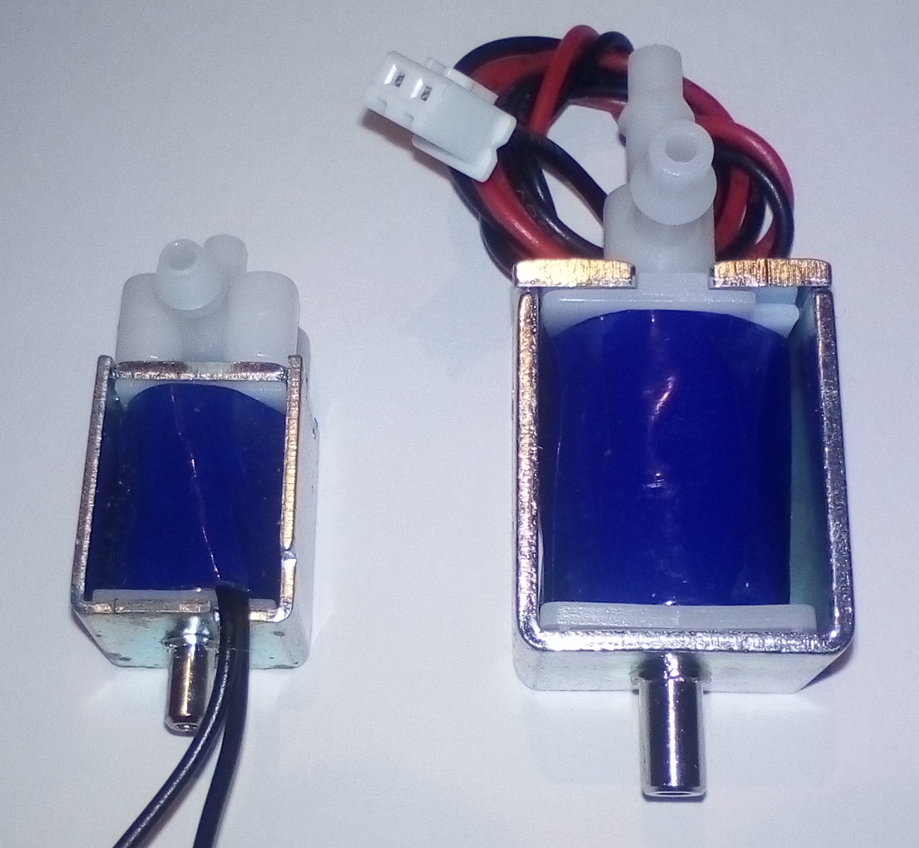
To control Vacum on two heads you need vacum solenoids that are driven my 6-12V signals. My PWM3 module is perfect for this.

As for Front Panel I am undecided yet, but I will need an on/off switch etc. It is possible that I can switch off power on the system leaving only a low-power module running to check power button etc.

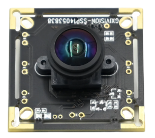
Camera Top and Camera Button is connected to Raspberry PI, so this is on/off and LED drivers – maybe 2 x PWM3 Modues?

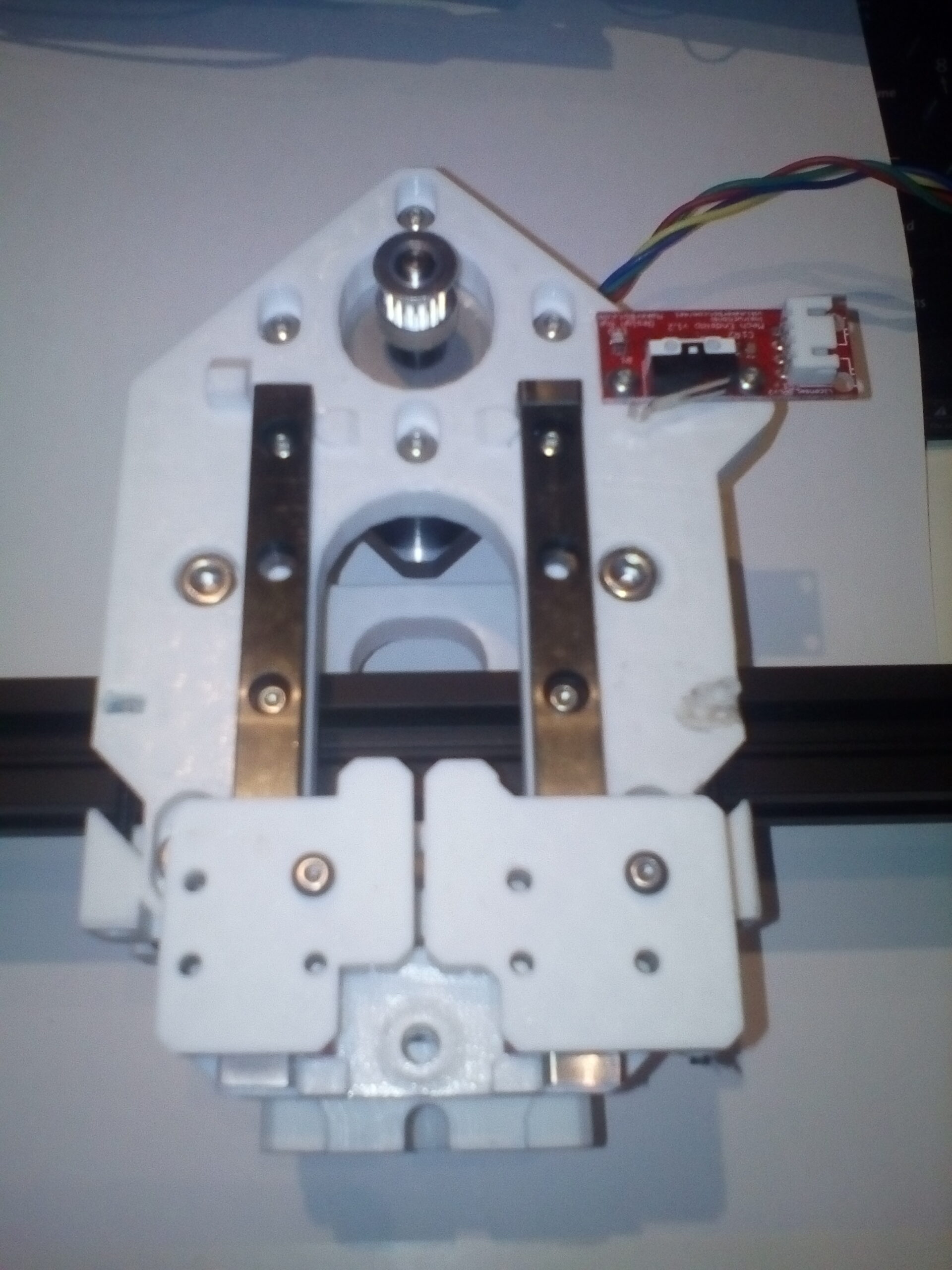
Calibration switches is digital input signals. I will need to make a very simple module with protected signals in for this.

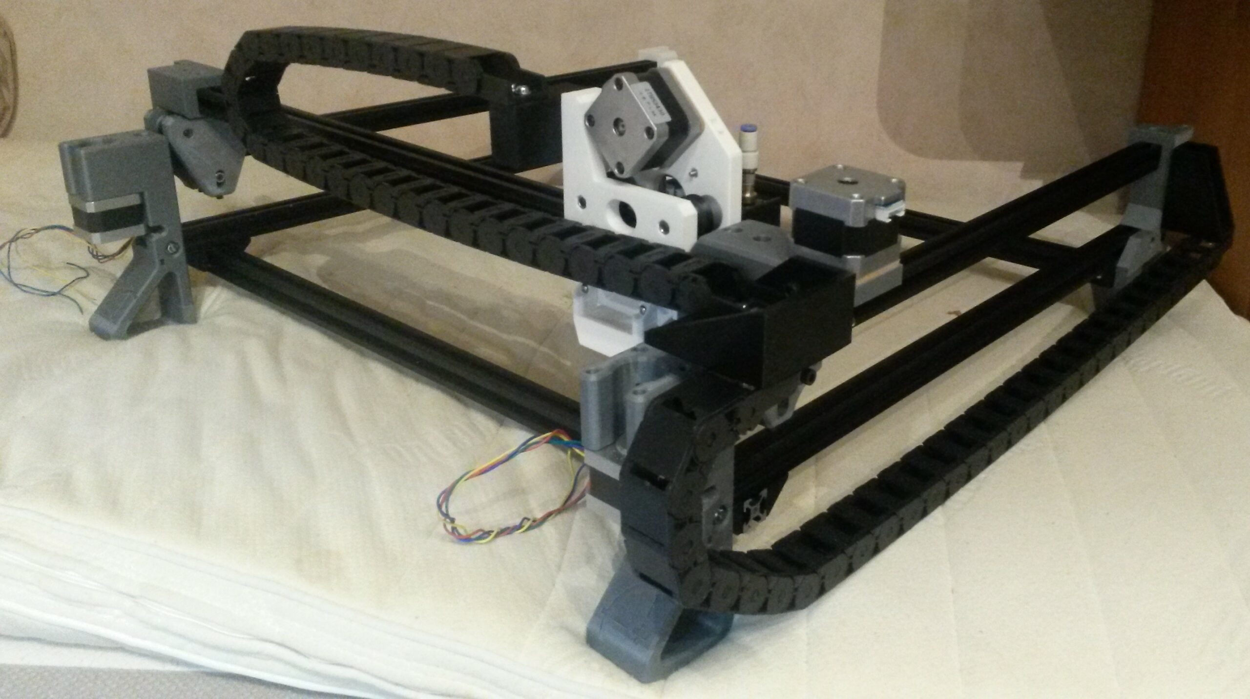
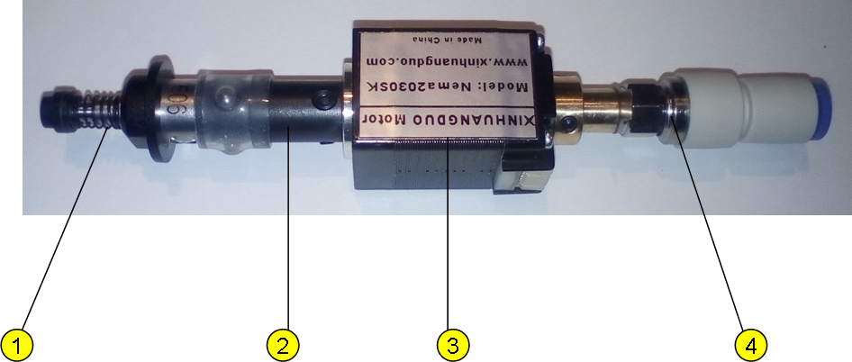
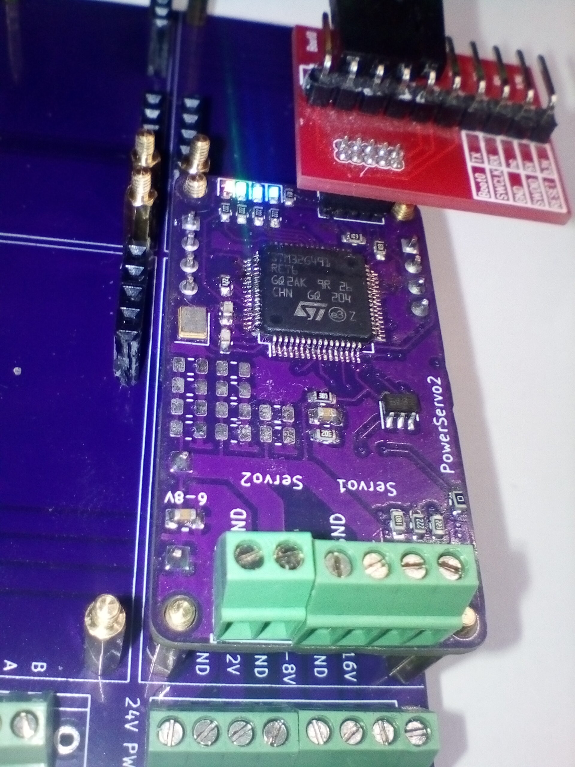
Stepper Modules are simple modules with one or two Stepper Hat’s. I will probably make a Single, Dual and Quad-Stepper module. My current PnP have 5 stepper motors since I don’t plan to mount the 6th yet (only single head for now) .

This is just an idea and planning ahead. To actually do this I will need to replace Marlin Firmware with a distributed version – it is very doable, but it will be a bit of work.

As for cost – multiple modules will cost more than a larger single module, but the bauty of this PLC is that I can use both. It is nothing that prevent us from making a larger all-in-one module with everything later and then still be able to expand this as we want. Also – cost of pre-made plug&play modules will always be a cheaper, easier way to do prototyping allowing you to make it work and optimize for cost/volum production after you have a success.

PnP – Back Legs

This picture is from LumenPnP (Opulo) that I use as base and show that they already have corrected the weak mechanical leg, but obviously not updated the open source drawing – or I must have downloaded the wrong ones 🙁

Never mind – I have glued the part that broke and they will do for now because I intend to change this design regardless. 3D printed parts have an obvious extra weakness in the direction they are printed, so if you print this laying down it will become strongeron that part, but notice that part that hold the motor – that would then be weaker and most likely break easier after some use due to vibrations over time.

I did notice that microsmt argue for having metal parts here due to this kind of problems with 3D printed plastic parts and I agree. This needs to be redesigned unless you want to repair your machine on regular basis. Sadly making metal parts is much more expensive. But, buying Aluminium plates are not – and one idea is to make hybrid parts – I want to redesign this part anyway because I want closed cabinets rather than a open dust collector.

PNP – First Mechanical Weakness

The red arrow show both the slice/print direction I used and where this part broke off. This is a corner peace and I needed to print it in two parts – that worked perfectly, but as I put the 2020 frame parts in I also accidentally dropped it to the ground and the piece broke. The design is a bit weak here, but the real cause is because I did not realize that the slice/print direction needs to go the other way to strengthen this exact peace. I then get the exact same problem on the right side on motor fixings – so I will print this separate in the existing direction.

This was a 14 hour print-job and I am almost done with the 2nd part, so 28 hours more of 3D printing to come 🙂

I will also see if I can modify this part to strengthen it because the stepper motor will be on right and cause hammock due to vibrations over time.

PLC – PowerServo2 Working

First I managed to solder on the MCU the wrong way and secondly I did not manage to solder some of the pins – I am seriously looking forward to having PnP machines doing this job, but my first module is finally working after ca 7 hours of manual soldering. Leds and SWD is working at least 🙂

This module was a copy of PWM3 because I wanted something to test my 60kg Servoees with. It needs to be simplified to reduce production cost. I am using a 64 pin STM32G491 here that cost ca 10.- USD alone and will look into replacing that with a 48-pin RISC-V that cost 0.4 USD and remove some components and move the rest to the front side. I don’t need both CAN and RS485 and I can remove SW controlled relays for the terminators by moving them down to a watchdog on the motherboard. I would like to keep CAN-FD, but might degrade to CAN-HS for now. I don’t need the capacitor bank and this as well can be moved to the motherboard. Even the FRAM can be moved to the Watchdog/Motherboard to simplify modules. I need to finish testing on this and do the same on Ethernet/PWM3 + I want to test RISC-V toolchain/IDE before I decide on WCH MCU’s.