I have lately had the priviledge of working with two vendors of mobile, electrical vehichles – one used a self-developed system designed for volume production series, the other was a larger industrial vehiche on prototy level where they started with a standard PLC and a small cabinet. Usage of a standard PLC “kind of works”, but you get a few challenges:
- Size – A standard PLC needs a cabinet and a lot of boxes to deal with all the sensors on a modern vehicle.
- Cost – each module cost from 100.- up to 5000.- ++ USD. It add’s up far to much.
- Functionality. A PLC is supposed to be easy to assemble and code, but old PLC systems might have limited capabilities, slow responce times and limitations on custom functionality.
- Lack of optimized volume production.
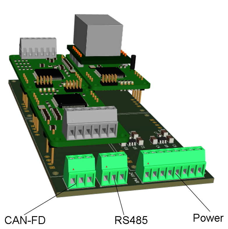
Some PLC vendors have worked on this and try to create smaller and more modular systems like the one I designed on this channel earlier. My latest PLC experiment was actually a big success, but it needs a few improvements. Having a Motherboard with add-on boards are great, but I can’t mount that onto any robot as is – I need to design a water proof box and I need to think about cables and noise.
First – lets discuss what a PLC actually is: Myself I am a software engineer more used to C/C++, electronics and embedded systems – basically I have spend a lot of years creating PLC modules as that is what they are. A PLC is only a nick name on off-the-shelf electronics that can be assembled and have a system to configure/code them to custom usage. An Arduino is in many ways a much better PLC module than many of the professional ones. But. PLC developers are also very focused on getting the job done and having a reliable installation. If you automate a factory with plenty of space you simply do not have the time to make custom electronics. But, if you design a product that will be selling/installed in volume you will be interested in two objectives:
- Getting the prototype assembled fast due to time to marked factors. An experienced developer knows that a product will not be 100% the first time because as you build a prototype you learn how to do it properly later. This learning is very important for the success of your product and so is also time.
- Having a path to a more cost optimized volume production.
The last PLC system I experimented with is a success as it offers this. It focus on size and special needs for larger drones that also apply for mobile vehicles. But, we need to move on and learn from the experiment to create a real series. I have summarized some lessons learned below:
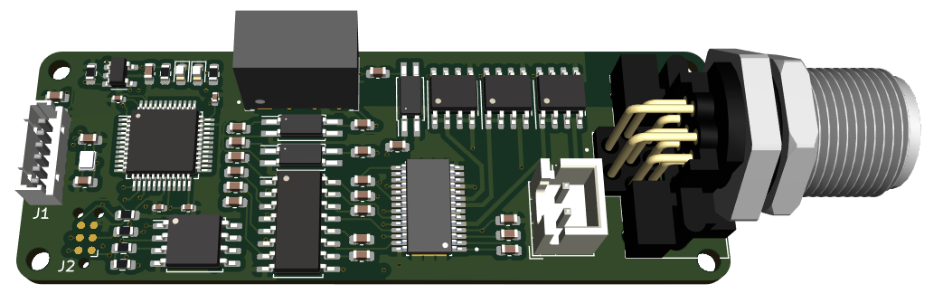
Lesson 1: I used a small 45x25mm format. I need to increase the size a little so that modules have space for galvanic isolation. Mobile equipment have a lot of wiring and a lot of motors that will cause issues, so we need galvanic isolation on everything.
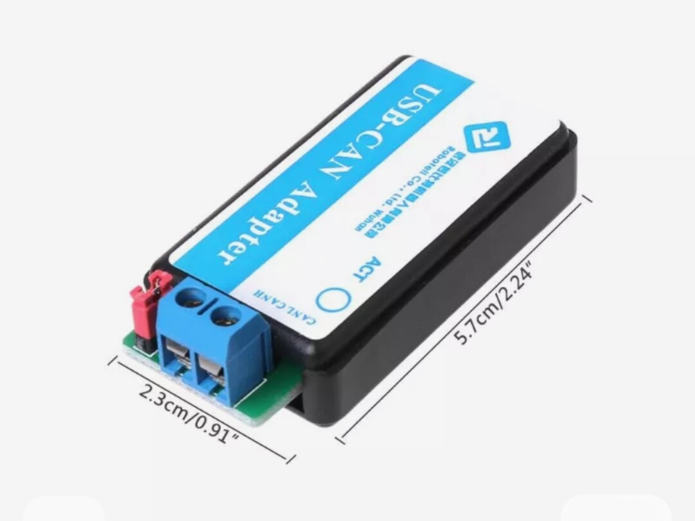
Lesson 2: CAN, CANopen, J1939 or Ethernet only. Wifi, BLE and LoRa is nice, but you can only have one of these activeCAN is excellent due to fast responce times and easy wiring of networks. CAN-HS is good, CAN-FD is even better. CANopen uses CAN 2.0A while J1939 uses CAN 2.0B so they work together + using standards means you can plug in 3rd party components then needed.
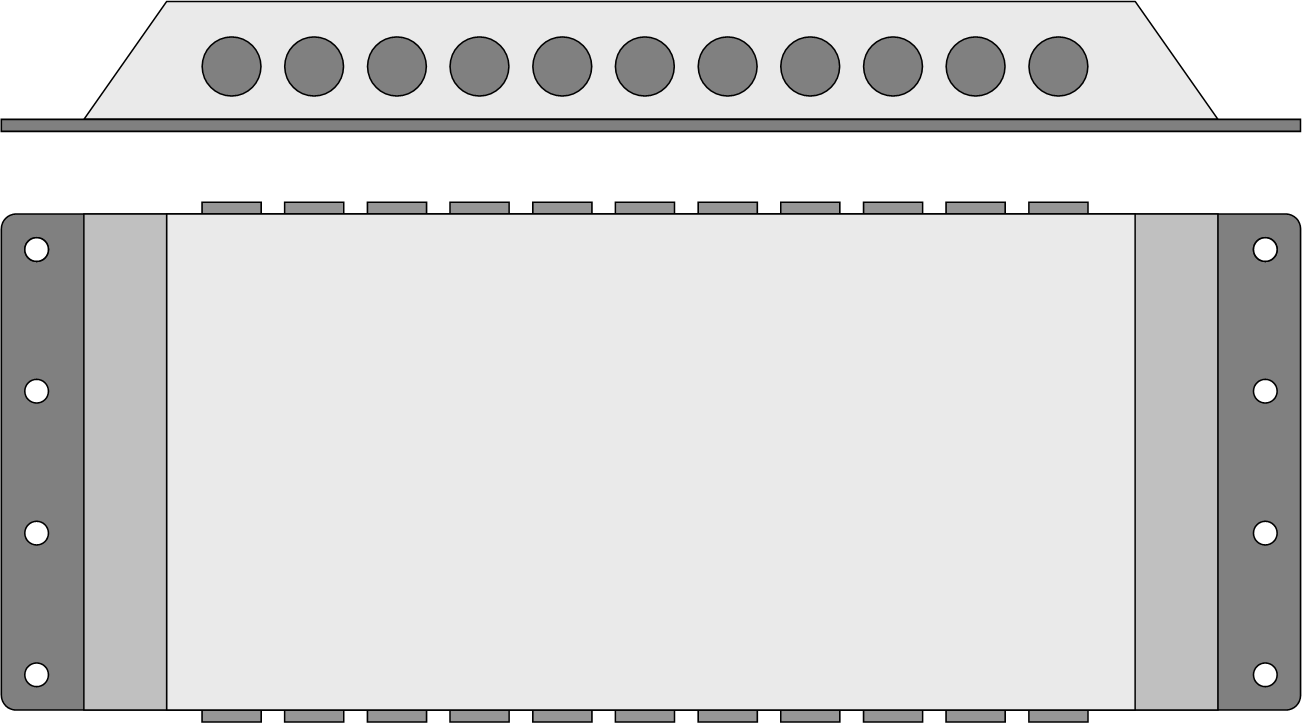
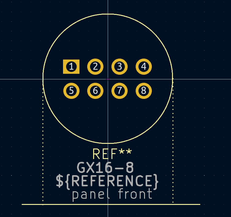
Lesson 3: Boxing and standard cables – minimize the need for actual wiring work. Use maximum plug & play to reduce hours needed.
Lesson 4: Galvanic issolation on everything. Modern electronics have a lot of new spece/cost optimized components for galvanic issolation, so lets use them.
Lesson 5: Motor noise – noise from multiple PWM wires needs special attention and wiring.
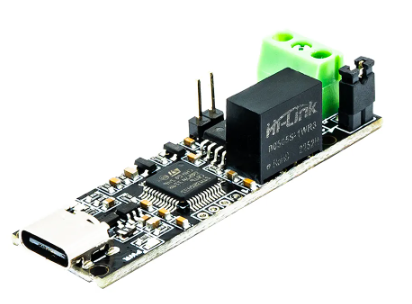
Lesson 6 : We need optimized motor controllers – Optimized in size. You can buy imverters, but they are often big and not to efficient. Cost is one issue, but space is critical – inverters tend to be much larger than optimized motor controllers. Also be aware that some car manufactores actually sell their car parts – motors and motor controllers at decent prices.
Dealing with electronics you will need someone to produce that electronics so you can buy it and use it. So having a modular, size optimized PLC alike system is worth a lot for prototypes. They allow you to assemble something fast and they allow you to change designs and adapt fast. Once you have a working prototype you should be able to create custom systems with a minimum of extra hours.
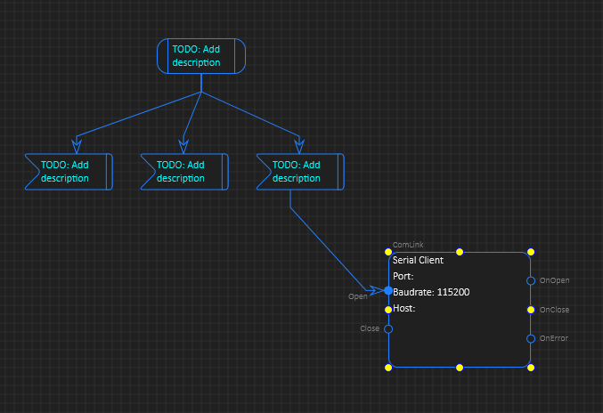
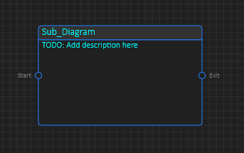
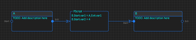
Software is a different issue. A classic PLC design is expensive in licensing and sometimes very limiting. In my opinion we often pay a lot for very little. You have close to no freedom using a classic PLC. But, that is where BSA comes into picture. BSA (BasicPI System Architect) is a more classic CASE tool where you have tools to create C/C++ code and use a mix of technologies to increase the productivity of a developer. It also merges the world of a old PLC with modern Software Engineering. But, most important of all – it has been carefully designed to have no limitations – if you want to write assembly or C/C++ go ahead – it is up to the used to justify your own time usage.
What I am considering is (1) Continue on BSA with more focus on a new PLC system, (2) redesign a modular PLC with learnings in mind and (3) start looking at motor controllers as part of a larger system.
Thanks for reading my early morning ranting – and I apologize for all the typos caused by a Norwegian writing English 🙂