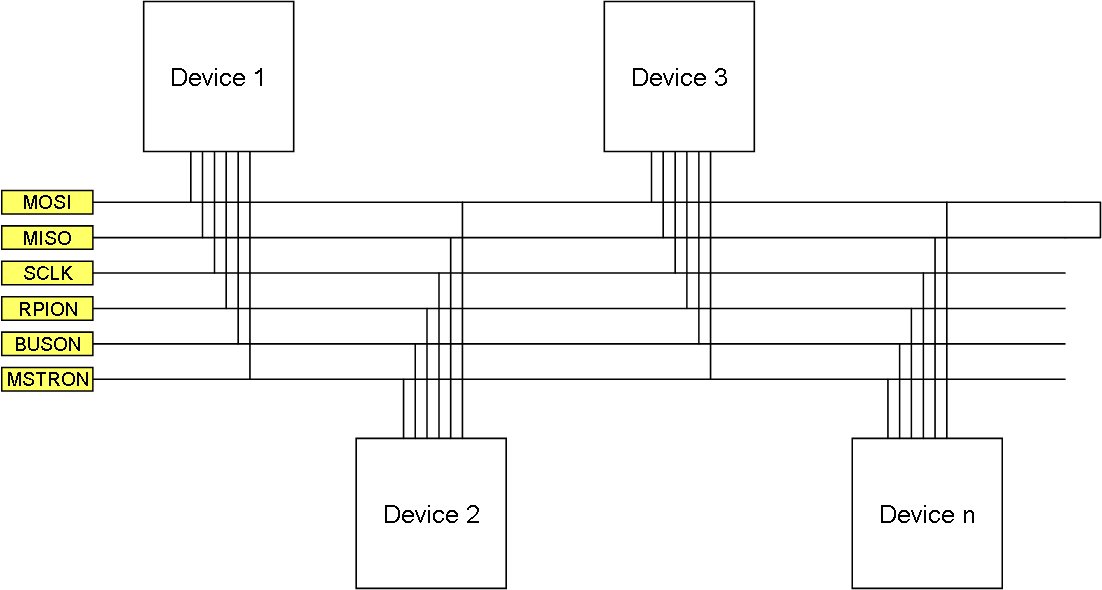
This illustration show the 6 signals currenty used for “Device Bus”. The 3 first are a standard SPI in Half Duplex mode. That means that one device is Half Duplex Master driving the clock and sending on MOSI, while the others send/receive on MISO. The extra signals are designed to assist in deciding whom becomes Network Master and to avoid collisions on the bus.
RPION was initially designed for RPI to pull this high, but we can as well call it “MASTER REQUEST”. All devices will silence the bus, stop sending and any current Master will switch to Device mode waiting for someone to re-start the clock.
MSTRON is pulled high by the master, meaning that if we have no master this will be low.
BUSON is pulled high by any device sending and pulled back low afterwards.
All pins are active high and will have a weak pull down. All devices should configure these as input pins until it is time to change. This way we will have no conflict if several devices try pulling high at the same time.
Once a device is started it will check if MSTRON is active – if it is it will wait. If it is not it will wait a random time and pull MSTRON active. We wait yet another random time and pull BUSON active as we transmit our ID. At this point we are the Master, but we also have damper resistors on SPI in case we still have a collision.
Starting an existing network is easy as all devices have stored their previous state – only the Master will attempt a Master start up while the other devices wait an extended time.
And yes we could have done all this is SW with SPI only, but I did not like the collisions I had – that said – this is only an experiment.