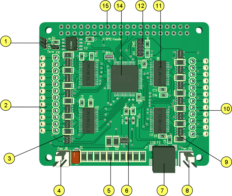
I have so many Hat’s by now that I try to make some systematic documentation on them. This drawing is part of what I call “Annotated Schematics” to document the design and collect notes needed for working on the Hat. This example is one of my more powerfully Hat’s as it contains 12 separate PWM ports with current sensors. PWM ports are actually separate Half H-Bridge ports with a GND connector each for maximum flexibility.
- Standard CAN port.
- 6 x PWM and 6 x GND connectors. Can use different terminals, but is designed for a right angle terminal to allow the Hat to be stacked.
- Current sensors. Separate current sensor on each PWM High Side, meaning we measure current out.
- Power connector for PWM supporting 60V.
- Capacitor Bank.
- Leds. One power led and one status led.
- USB port.
- 5V Power.
- Current Sensors.
- 6 x PWM and 6 x GND connectors.
- PWM Drivers. In this case I use DRV8301 that contains 3 x separate Half H-Bridge drivers. This can be combined to drive 12xindividual PWM signals of 60V/2A, 6xDC Motors, 4×3-Phase Motors, 3xStepper motors or any combination you like. Each of the DRV8301 have power pads connected to back of the PCB and I can actually mount a heatsink on this one if needed.
- Standard SWD connector.
- na
- STM32F405RG
- Raspberry PI Connector with SPI Backbone and 5V. Enables the Hat to be used with Raspberry PI in a stack, stand-alone or together with other Hat’s.
This Hat is so powerfully that it replaced a lot of other Hat’s I planned. I was considering a separate Stepper Motor Hat or DC Motor Hat etc, but I don’t see the point. This is one of the most flexible motor drivers I have made. If you go back on this blog you will also see my notes on how many attempts I made on routing this before I succeeded. So far it is only minor comments on what needs to change.
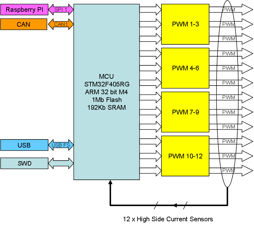
This show another part of my “standard” documentation, the functional block diagram. This is basically just a visual content list.
I have done PWM signals before, but I am looking forward to experiment with the current sensors. If I use current sensors on a Stepper I should be able to sense torque and automatically detect edges etc.
The reason I started assembling this now (it has been around for a while) is however x-mas coming up – powering multi-colored led string.