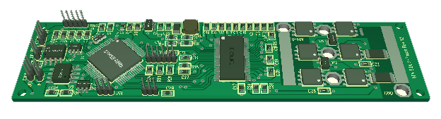
This is my 3KW 3-Phase Motor Driver Rev 1.3. Revision 1.0 and 1.1 had air wiring, 3 current sensors and output at right. Rev 1.2 lacked RS485 while Revision 1.3 have CAN and RS485 + 2 temp sensors between MOSFET’s + I solder on cobber wires directly on PCB for 60V and GND to sustain 50-100A. The actual rating for the MOSFET is 160A per MOSFET, but my math indicate we can sustain 50A continuous due to PCB and Heat dissipation.
The VESC (Vedder design) uses more powerfully MOSFET’s, but is also limited to 50A continuous due to heat dissipation. My design allow for a heat-sink on the back. My math indicate that I reach ca 1W dissipation at 35A per MOSFET, so I should be able to sustain 35A continuous on single channel. But, using a 3-phase you have 3 channels and as the limit here is dissipation per MOSFET it should be 35A *3 /2 which is 52,5A before I need a heat-sink. Adding the heat-sink I hope to reach closer to 100A continuous, but you have to take these numbers with a pinch of salt + With 100A continuous (which means average) I might be touching the 160A pulse limit and start overheating PCB lanes – so 50A is the target for a reason – for now. I have seen smaller designs that claim 5KW etc, but they kind of “forget” to mention that you need a shitload of heatsink/fan Attached. My objective is to achieve this with close to no heat-sink due to total size.
I have 3 motors I can test + a 4th on it’s way. Comparing this to the 3KW Universal Driver I have the opposite challenge – I actually could need far more power (Ampere) though this stick to drive more powerfully 3-phase motors available at decent cost.
I have renamed this to 3KW Thunder Stick – size is 100mm x 25mm which is perfect as I get finished heat-sinks and it is more or less an extension to the wires, easy to hide on a drone.
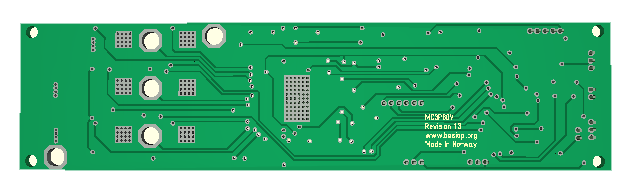
This shows the back-side where the heat-sink will be added. The MOSFET’s and DRV8301 both have pad’s underneath, so the heat-sink will cool them down as well as cool down the PCB itself. All wires (60V, GND and U,V,W will be added on top. power capacitor will be soldered directly on power cables. If heat-sink is not needed I can move the cables to bottom – I can also Mount a Shorter heat-sink on top thought I currently lack mountings holes to support that – but we will see.
I have delayed ordering this PCB because my backlog is so large, but I will order it now so I can test fundamental concepts + mechanical fittings.