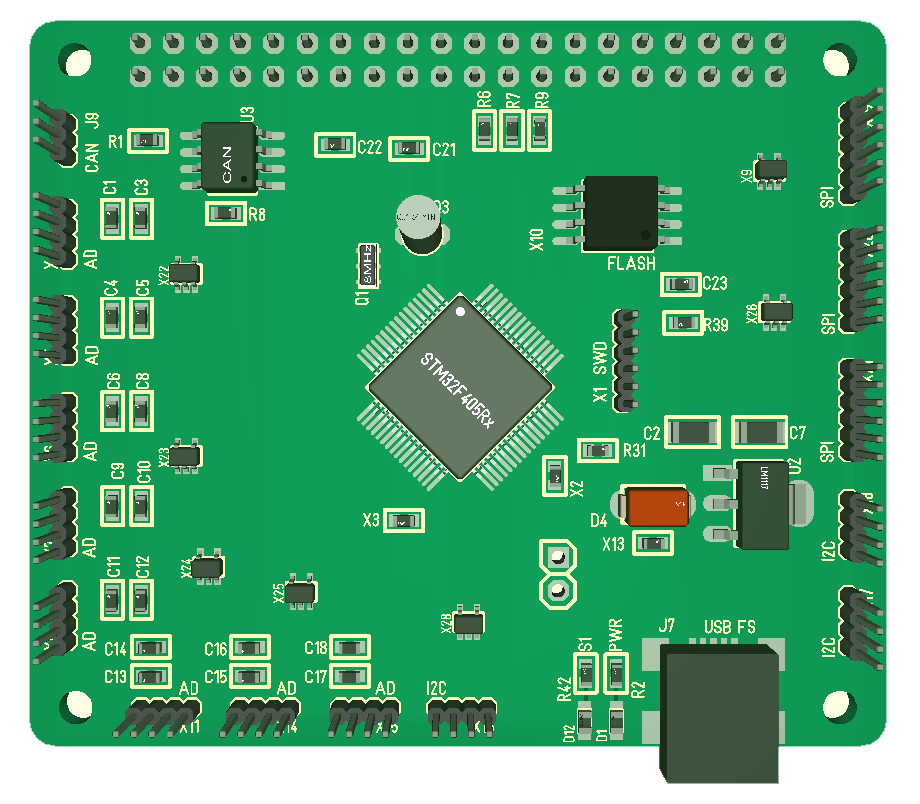
I have still not routed this, but schematics and component location is getting in place. I have to make a package for CR1220 battery holder for RTC + I would like to make the proper packages for the connectors as well. I dropped the extra CAN and RS485 due to lack of space + I have other cards for those. I also ditched SD card due to lack of pins, but I still have the SPI Flash.
I also have to think a little about what Power I feed out on the ports. I am currently using 3.3V, but I want to add a jumper to select between VIN and 3.3V for the Hat. Ideally I should have done that per port, but that would require 30 jumpers. It is possible I can manage separate for AD, I2C and SPI. Many of the available breakout boards uses 5V due to Arduino, but that said our AD ports do not have 5V tolerance.
STM32 have a lot of 5V tolerant pins, but analogue pins that I use on AD ports are 3.3V. So giving 5V out then you only can receive 3.3V signals might be a conflict. I could add a level shifter, but I actually think I prefer to stay with 3.3V. As always – work in progress.
My backlog of designs I want to do and PCB’s I need to work on is getting huge so I decided to be a bit more systematic and make sure I do proper doc on each design. The “doc” I use is a small document I call “annotated schematics”. It basically take the schematics, block diagrams, 3D models etc and add some notes to them in a paper. If I do a Revision it will add a list of changes to the previous revision etc. This doc only takes a few hours, but it is worth gold a few weeks down the line then things have been forgotten.
The backlog of designs will continue to increase. The main reason for this is because I find it quite relaxing to sit and work with schematics/PCB routing in spare moments. SW is a bit different as it is more complex and require Focus.