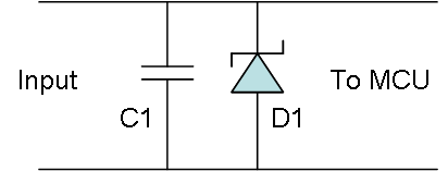
This little circuit show the passive protection I want to add to each analogue and digital line.
D1 is a TVS diode set to ca 5V, meaning it will suppress spikes above this level or negative spikes. This is the real light-weight protection. The drawbacks with a TVS is that it takes time to activate so we give it a bit of help with C1 + it can only suppress an overvoltage for a very, very short time. It is not a galvanic isolation.
C1 basically act as a low pass filter and need to be calculated correctly to a cut off point. This being a small capacitor will take the spike out of the spike giving the TVS time to switch in. Together they should provide a very decent protection on the MCU, but they do come at a price.
- Analogue curves might not be linear as we get closer to 3.3V or 5V because the TVS start kicking in. To compensate for this we usually select a TVS that is 5V for 3.3V or similar.
- Extra components take extra space on the PCB and C1 will also affect input signals a little.