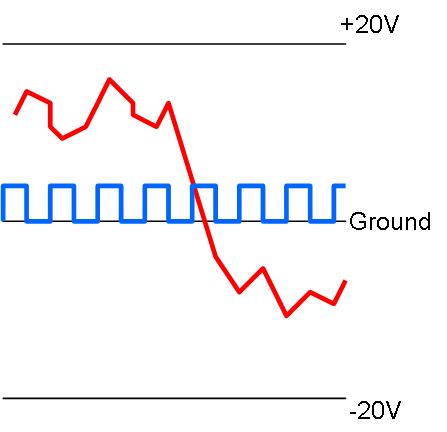
This illustrate the main functionality I want to achieve. The DDS can generate waveforms as well as more classic squares, triangles, sinus etc. I would like a signal that can be amplified to +/-20V and given a base offset anywhere within that range.
The blue line illustrate a more classic square signal starting at 0V, while the red line illustrate a programmed signal with any values between +/-20V.
I think +/-20V is a nice objective and I will settle for 100mA out. AD8008 offer me a max 12V signal, so if I use that I will have to settle for a 12V delta positioned between +/- PSU boundaries.
In fact – LM317/LM337 have +/-36V as a range, so I should be able to achieve a compromise if I can amplify the signal from the DDS to 12V Delta and adjust the base offset to -30 to +30 or something. I think this offset adjustment is straight forward, it is just that I have not done it before. I realize that I am a bit inconsistent as I draw +/-20V and talk about +/-10 to +/-30V. I will go for +/-30V if I can, but I will settle for +/-10V if I must. I will also go for 1A out if I can, but I will settle for 100mA out.
Selecting a DDS chip is something I will return to. I indicated AD9851, but it is a long range of chips with frequencies up to 1Ghz and various functions. Their pricing range from 5.- USD to 50.- USD, but these are key to generating functionality at decent frequencies.
Selecting amplifier is the same. AD8008 is a candidate, but I would like a chip with a larger voltage out and preferable digital gain and offset. The more I can get packed into chips the more realistic to get this all on one Hat.
Having this on one Hat is an objective, but I will settle with DDS on one and Amplifier on a second if I have to. In fact – I wonder if I could benefit from 3 Hat’s – One DDS with 3V out, One more capable low frequency amplifier and one high frequency amplifier. Having these as Hat’s have values of their own + the Hat system means I easily can add as many channels as I want on the actual function generator.
It is a lot of loose ends, so it will be some time before I can settle a design that I am happy with. I am also a bit on on the edge of my own skillset here so I have asked someone who consider this “babyfood” to assist me as we move forward.
One main concern is PCB layout. I think this needs to be my first project using 4 layer PCB.