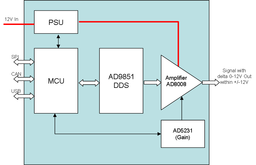
I think I can achieve a decent function generator by combining AD9851, AD8008 and AD5231 as shown above. AD8008 is an amplifier with 650Mhz bandwidth and it uses a resistor for Gain adjustment – I think I can use AD5231 for that purpose. The Voltage input is max 12V so I should in theory be able to deliver 100mA on a programmable signal from 0 to 12V out.
I seriously would like +/- 10V (or even +/- 20V), but the last amplifier stage is difficult to achieve with both frequencies and space intact.
I earlier mentioned using a programmable resistor to control an analogue PSU input and this is still an option. Assuming the 12V in is isolated I could use LM317 and LM337 with a dual potentiometer to programmatically set ground out. I basically trick AD8008 to believe it has 12V DC, while I adjust ground out to be anything between 0-12V giving a signal that can be 12V size between +/-12V. I think this is possible, but I need to experiment a bit on what I do here.
Size and frequencies are a main concern, so it is possible that I maybe should split this into 2 Hat’s – one with AD9851 and one with AD8008 and the PSU part. Frequencies are – well – 50-70 Mhz out will be nice, but I am happy with 10Mhz as a start. The issue is that once you start dealing with 50ich Mhz and higher you also start to get into high frequency concerns on the PCB.
This actually starts looking possible – I think I want to start with the PSU part – simply use 2 x AD5231 and see if I can achieve a programmable +/- 12 V out the way I hope. The next step is to verify that I can use a AD5231 to adjust gain on AD8008.