I started to mechanically assemble the 4 channel 3KW controller. One note is that 2mm wire is easy to work with, while 3mm wire is very hard to get right. In fact, to assemble this it might be better to design with 2x 2mm wires than using a 3mm. I have not started with components yet, I am just making the mechanical wires ready. All in all it went easier than I feared, but I still have some wires to prepare in the middle so we will see how it goes.
Just to remind everyone – the 2-3mm wires are to support 50A out.
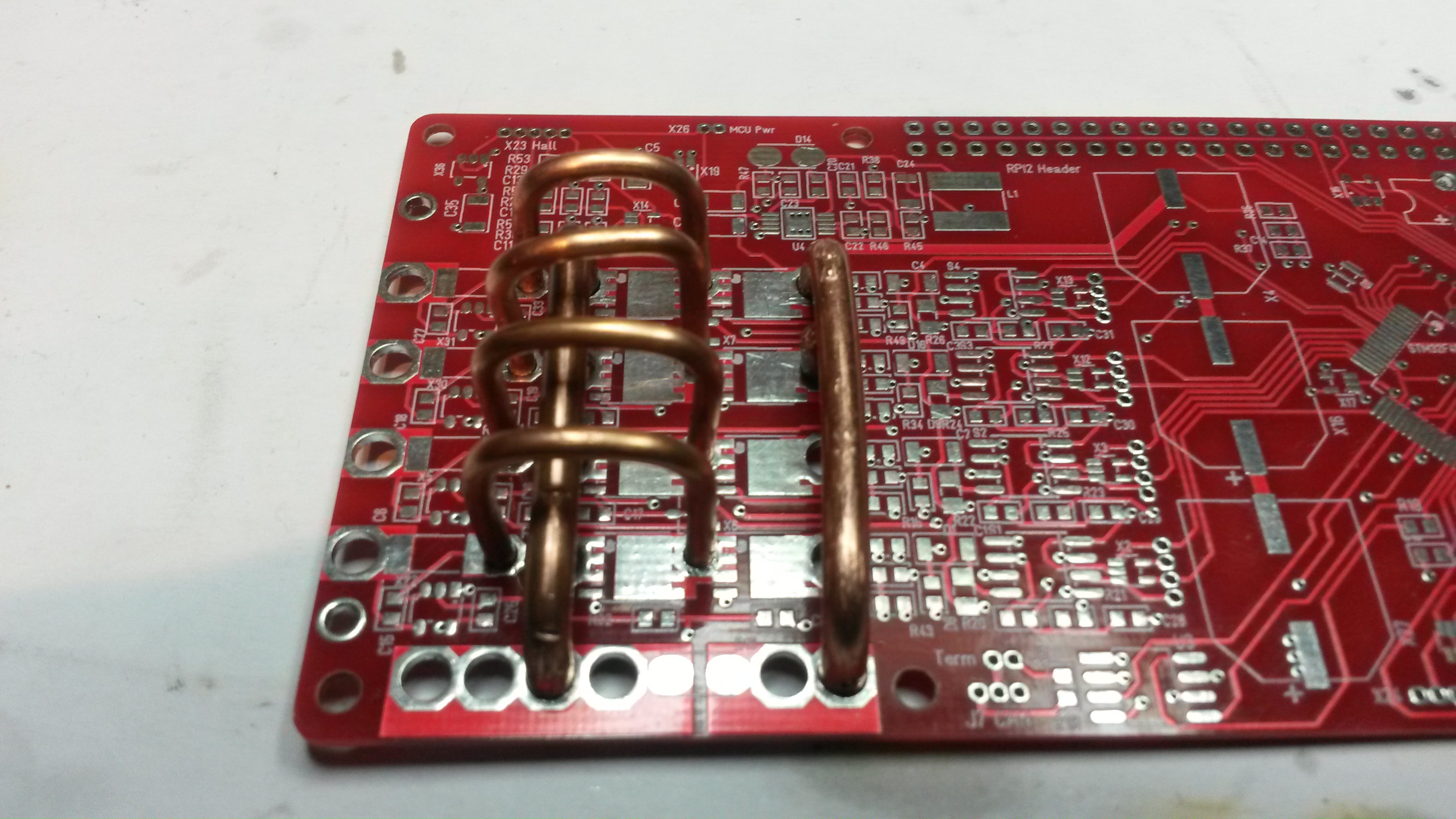
As can be seen on this pictures – these boards have a major design flag. You can see the square pads that will solder to the pad’s of the wider SO8 MOSFET’s, but what is missing is the array of went holes to the back-side. This should have connected the MOSFET’s to the back and used the ground plane as base heat-sink + enabled us to connect a heat-sink that was connected to the MOSFET’s. Without this the MOSFET will heat up far to fast, so I am not going to attempt 50A out of this yet. But, we should still be able to manage 20-30A out. For now I just want to assemble and test the unit. I lack both motors and PSU for heavier load testing anyway yet. I will send for a modified revision as soon as I have some experience from this.
What I am most curious about here is to test the new super-MOSFET’s supporting 60V and 160A with an insane 400A pulse drain + temperature sensors and current sensors. I have a ducted fan 12V/30A + a 12V/15A motor, but I need to increase my arsenal of test motors.