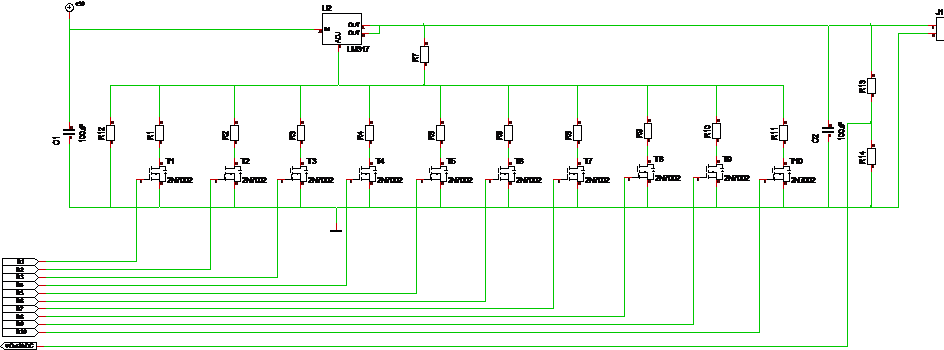
This weird circuit is a programmable, analogue PSU. It is basically only a LM317 and an array with resistors and MOSFET’s so I can program the voltage out by selecting a combination of 10 resistors. This is not straight forward, but I can at least Select 10 preset values. In addition I use an ADC to measure actual voltage out. I need to calculate resistor values, but this will work just fine and solve my challenge with how to get a programmable PSU for a function generator.
R7 and R12 decide the max output voltage. By switching on/off MOSFET’s you change the voltage divider adjusting LM317 and hence the output voltage. This is not the most elegant PSU, but it is analogue avoiding the challenges with switching noise on a DC/DC regulator.
To get a negative voltage I do the same with LM337 and a different MOSFET array, but I will get an additional challenge I need to divide input voltage. Assuming I have 24V in I can establish ground out on 12V and have a circuit that output +/-12V. To do this I also need to ensure that signals to the MOSFET’s have correct voltage using the new ground as reference. I think I can get away with that by using the new ground as ground for the MCU and AD9851 as well.
I use 2N7002 in the example above which cover 60V in SO23-3 package, but you can use any N-channel MOSFET. LM337 needs to be associated by P-Channel MOSFET’s I think. This circuit is excellent for a breadboard test.