I am returning to this board to make a new attempt because it is a very attractive board to make + I just received another bunch of DR8313 chips and Connectors that I need to use for something. What stalled me on the last attempt was several issues:
- 12 x current sensors are a bit hard to route and I basically forgot that I needed wide power lanes, so I need to make space for them.
- DRV8313 is rated to 2.5A in peak, meaning that I can’t get 2A out per channel as that would be 6A per chip.
- Space in general.
The 2.5A limit is worst for PWM stand-alone signals, but the actual target is 1A and I can always combine output’s to achieve 2A. I need a bit of testing, but I think that will work just fine. 2.5A is just fine for 3-Phase and Steppers. The one drawback with steppers are that we need to do a bit more logic in code, but we have the MCU capable to do that and I want a stepper with current sensors.
The one thing I need to test is the current sensor. INA194 have a very attractive footprint and voltage range, but I am a bit concerned about it’s datasheet. It basically need 50mV input before it become ca 1% accurate and with a gain of 50x we basically run out of 3V range at 60mV input. I also use 0.25W shunts to get 1206 footprint (size) so it’s not straight forward to decrease gain and increase shunt resistance as I start using to much effect.
I also need to test currents through DRV8313 and I have a small 3-phase that I can use for that purpose. This is a simple test to run constant current and use a finger to test temperature to see what I can get away with without a heat-sink. But, heat-sink is actually straight forward because DRV8313 use a pad connecting to ground so we went out on the back-side and can add a heat-sink directly to the PCB.
What I will do is to mount INA194 on the breakout boards I made earlier and test. The reality is that I don’t need current sensors to be that accurate, but I need them to indicate levels on low currents (50mA and up). Used on a 3-phase that helps me detect rotor position so I can use vector based algorithm’s. And for a stepper it indicate torque so I can detect end-stops without an external end-stop sensor on CNC machinery.
I can easily make a separate 3-phase, stepper and PWM board, but the combined functionality of this board makes it very attractive to implement it. I can always go into 10cm width to get more space, but I want to make one more attempt on the current size format first.
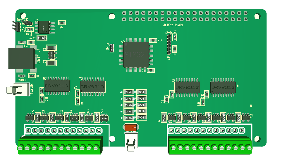
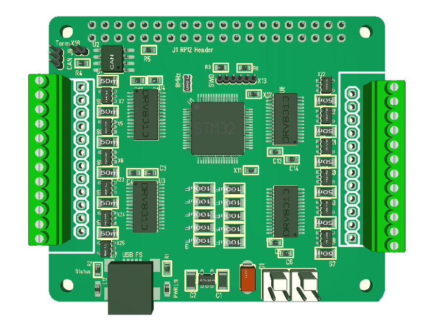
The different approach I want to try is to move the connectors to the left and right and have USB/Power in the middle. I believe that will allow me to get away with less space around the MCU + I get 2 x DRV8314 on each side.
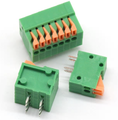
As for space – the connector account for a lot here and I could get away with a lot less if I made a specialized 3-phase or Stepper Hat as I then would use right angle Micro JST connectors. It is the need for a combined connector that made it attractive to use this footprint. But, I also notice that the smaller JST Connectors handle less mechanical stress. The connectors I use here have 2 pins per channel to handle to make them more robust.
The 10cm wider board will need different width of these connectors, but as I get more space I could also consider adding galvanic isolation between Driver and MCU. We are after all dealing with a lot of effect and coils here and I will need about 6mm to support an array of photo couplers. A quick look at the mockup below indicate that this actually might be possible.