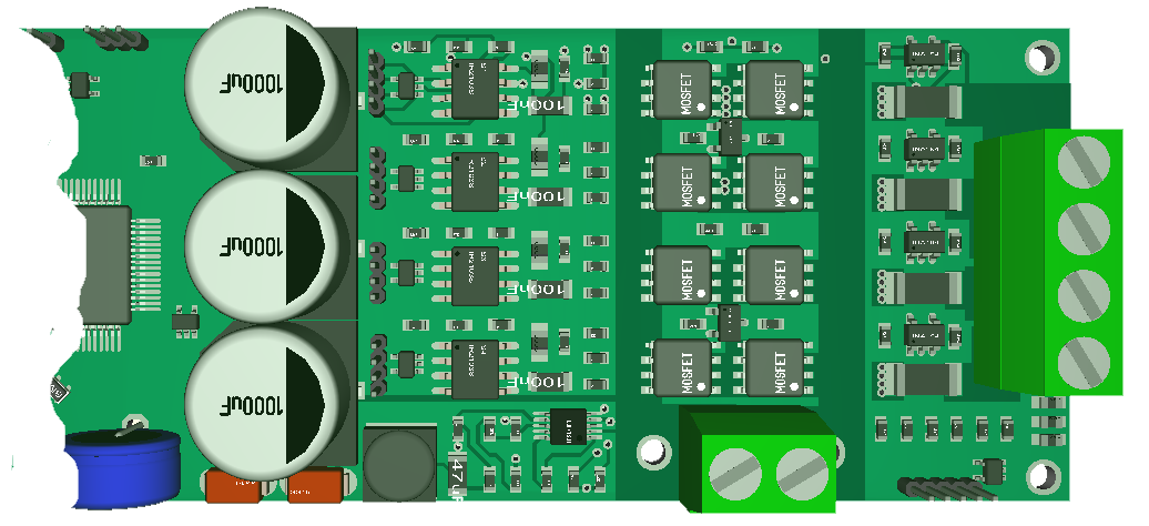
Always funny to share 3D models. This shows the right side of the new 60V Universal Motor Controller. I have spaced out the MOSFET channels and moved all components top-side as well as added 2 temperature sensors, a new 60V DC/DC, capacitors on board and enabled JST channel connectors. I have routed 1 channel, but need to route the 3 remaining (copy) and then comes the big question.
To support more than 15A I need to lay down solder tin on the paths up from the power connector and I also need a wire from the between MOSFET’s to right side of the shunt. I will in reality need 2x3mm holes for that wire and I need to find those 6 mm. If I push those capacitors further to left I will have no room for MCU or I will need to exceed 100mm. One alternative is to push the right power lane to bottom that is ground plane anyway.
I am very happy with MC4X as is, so I am looking forward to this modified board that deal with the remaining issues. It will still be work in progress for a week or so, but I think we might be assembling this during x-mas.
So will this be a 1KW, a 3KW or even a 6KW design? As Is we talk about 60A @ 15A per channel – that is 3600 Watt limited only by power lanes. If I increase to 50A we would be talking 12KW – again the real limiter here is not each channel but those lanes feeding each channel. 12KW would require support for 200A – so no – it is not impossible, but it would require some more space – lol. It is just funny to think that it now should be lanes and wires that limit this design. This amount of energy from a 100x40mm board is insane!