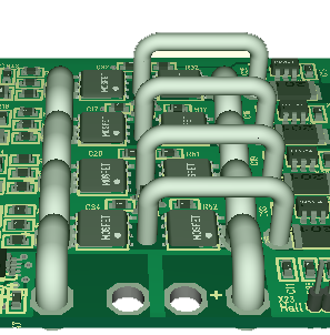
I decided to remove some of the PCB lanes and replace them with high current wires to support 50A currents. I had to extend the board ca 1.5mm at right, but to compensate I also remove the connectors because I need high current support all the way. I like having connectors for <10A solutions and playing in the lab, so will see what I can do. This will also free up 2-3mm that I desperately need at left.
At the end it simply made no sense to continue with 15A limit as I realized I would be using the same components and same space for a 50A design. And yes – this is a 50A design. The power wires are 3mm in diameter that actually is something like 64A while the 2mm wire for each channel is ca 41A. But, in addition to this you also have heat-sink at bottom as I connect the PCB itself to the heat-sink. I am confident that I will get sufficient out of this board.