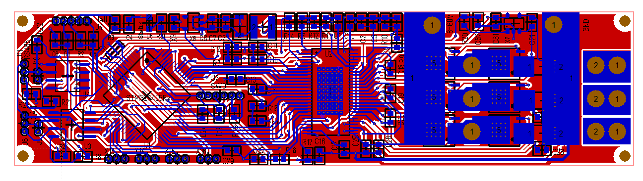
This one was not as hard to route as I expected. I had to do a few compromises and I need to look things over. Ground plane include a few lines that I want separate etc + I need to ensure that all ground planes are connected. But, this looks good. A bit to dence and I really could have needed 4-6 layers here for analogue signal quality.
- Size 100x25mm
- 8-60V / 50A capacity
- STM32F405RG or STM32F105RB etc
- RS485
- CAN
- Hall Sensors or Encoder port
- 3 x Current Sensors
- 4 x IO ports (3 analogue capable)
- DRV8301 based
- 160A MOSFET’s
- Components on top-side only.
Returning to my 24V/15A design it is actually the same SOP-8 sized MOSFET’s, so as soon as I have tested the 60V DC/DC and current sensors I will upgrade that as well. I need to decide if I want to leave it at 24V or upgrade to 60V or increase current capacity.
Looking at MC3P60V50A above you can also see that close to 33% of the board is DRV8301 (Gate Driver). This is 2 cm longer than MC4X24V15A, but more narrow since it has 1 less channel and did not need the separate DC/DC. Components on top-side only is a big win.
Printing this one out on a printer is actually scary – it is much smaller and denser than I realized, but this will be fun to play With.