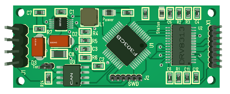
This is a 3D model of my new BLDC Controller “MC3X3ACAN”. 3X means 3 separate Half H-Bridge channels, 3A means 3 Ampere- it is actually 2.5A max with 3.5A in peaks. This design does not include current sensors, but I have Hall Sensors since this is my target and better for low speed applications. I decided to skip current sensors, supercap and serial memory to get size down. I would have needed ca 2 cm more for that. But, I am also aware that currents sensors are very difficult to use on small motors at low speed, so it’s not a big loss. The 3D model shows STM32F303CB, but I will double check that I also can use STM32F103CB/C8. I have never used F303 before as well, so this will be fun to test!
The size is 50mm x 20mm and I am happy about this knowing that this is a 60V design with hall sensors and all components on top-side. I am not fully finished as I need to squeeze in capacitor mounting holes at left + I would like a few extra IO ports on a JST Micro Connector.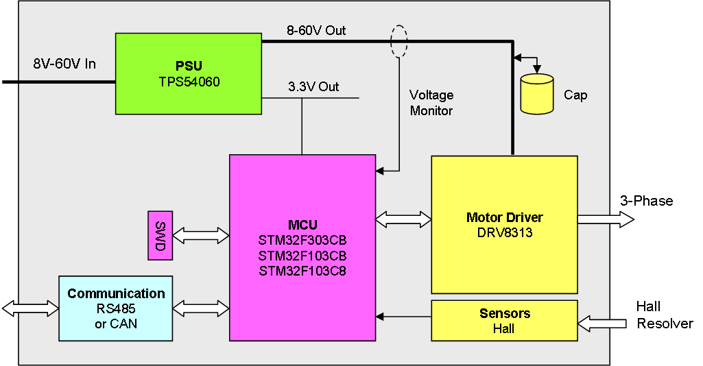
I used CAN on this for a change, but the focus here is to test my DC/DC converter as well as DRV8313. The big win is that this has all components on top layer allowing me to use the bottom layer as ground plane. Yes I can do that regardless, but I try to avoid ground planes on component sides because I get short-cuts easier ase I hand-assembly these for now. Replacing CAN With RS485 will only need 2 extra resistors.
One option that will require a bit more space is to replace STM32 with ESP32 and test the Motor & Hall Interface on ESP32. That would be a cool device with full Wifi and fun to experiment with so I will find time to do it.