PLD – Executable Logic

The diagram above is a minimum PLD function similar to classic, empty functions. The only challenge here is lack of executable details.

This 2nd diagram show one way of presentaing executable details. This is key to our success, so we need to work a bit on this.

This last diagram show a possible single-step debugging technique. Notice that we display variable values and highlight diagram parts that is the next step. Again – we need to experiment a bit with this to see what works and what doesn’t.

Plain Logic Diagram – Terminator

I did a few prototypes to test a graphical programming language a few years back. First one in VC++/MFC and later one in C#/.NET. What I will do next is to write blog entries discussing the syntax and wrap this up as a language specification.

I called this “Plain Logic Diagram” (PLD) by accident and I will use that name for now.

We have already described Plain as an assembly language, so this is a “compiler” that generate Plain assembly. The syntax is based on a combination of classic Flowcharts, SDL (Specification and Description Language) and some new concepts to take advantage of graphic diagram qualities.

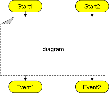
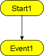
The illustrations I use will have to be created in various tools, this one show the terminators of a diagram and is drawn in PowerPoint.

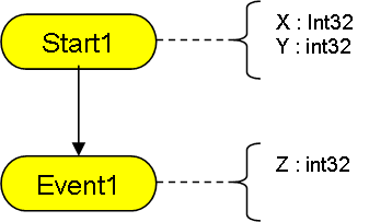
A classic function have a start and an exit. We already know that Plain raise events with different output parameters. In the diagram this is shown as multiple exit terminators with associated parameters. The new part is that we also have multiple input paths with different parameters in the same diagram.

The key principle here is that one diagram is a function with multiple entry points and multiple exit points. Exit points are event’s that either are Static, Optional or Mandatory.

A Static event is a hard-coded jump to another diagram that can not be changed.

An Optional event also have a hard-coded default that the user can chose to override as he uses the function.

A Mandatory event must be present in the diagram using the function.

These are the same principles we decided on for Plain assembly events. In the real diagram we will add notifications to visualise these.

A diagram is the same as a “function”. Off-page connectors can only be through terminators, but a diagram can be as large and complex as you want. Logic is flow-chart like and will be instantly recognized by most people. This diagramming technique have been tested as executable specifications and have proven itself as a superior specification technique in front of customers. The only drawback is that you need a specialized tool to do this otherwise you just end up using far to much time creating diagrams.

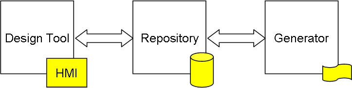
So in short – the IDE and language goes hand in hand. A graphical language can only exist if we create a proper IDE/Tool for it.

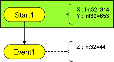
The diagram example shown here do however suffer from the issue that I can’t see the parameters. I see high level logic, but I don’t see the actual executable details. Also – what about local variables etc?

to be continued…

Tool Design Concept

I tend to stick to a single, simple concept as I design tools regardless if this is Compiler, Assembler, HMI Designer or something else – I create a tool, a separate Repository and separate output generators as illustrated below:

This means that the tools (like HMI Designer) will store it’s output in a repository database which is in XML format. As this can be read and manipulated by several tools it allow us to easily create a larger, integrated tool package with multiple design tools and code generators working together. This is how modern CASE (Computer Aided Software Engineering) Tool should work.

A second, key prinsiple is that source code is stored in ASCII format editable by simple editors. In this case the repository is stored as XML. The reason is simply that you need ways to recover your project manually if files or tools screw up.

Some years ago I worked on a new tool that also stored it’s work as XML files. One of my projects was a total of ca 1300 files with cryptic content. And as this was a new, unstable tool created in Eclipse it crashed ca every 2-4 hour of usage destroyed it’s XML files. Recovering this manually was possible, but not realistic so I ended up manually backing up everything every 2nd hour. A file system is an excellent undo system and it cost very little to add a backup folder where the last n versions are saved. This way, if the project screw up you can chose to pick up the last saved version. Tools can easily do this automated, something that saves the day if disaster strikes.

Graphical Programming Languages

One of the objectives with creating a diagramming framework in Qt is to be able to create some tools that can support classic desktop look & feel and be re-deployed on Web, tablet’s & phones. I want to take advantage of some experiences from Web based technology, but as mentioned before – I develop network centric control systems, not stand-alone devices.

Creating a HMI designer that makes it easy for anyone to create advanced user interfaces with little or no specialized GUI/Web development experience is the first step. The next is to mature this and build our own tools to support Plain/easyIPC.

One of my objectives is however a fully graphical programming language to sit on top of Plain. Obviously we need something like UML class diagrams or classic ERD to model data, but I also want to program logic using graphics. Tools like LabView or classic CASE tools already does so with some success.

The challenges with any graphical programming language are however often a surprise to many.

A graphic diagram makes things look easy and can easily create a delusion that using the tool also is easy. As most programmers will tell you even the simplest text editor is far faster than any graphic editor in creating logic. Your programming speed will initially drop by a factor of five, meaning that before you can benefit from increased productivity factors you need to compensate for this major disadvantage.

Choice of graphic language is often poorly made. What I will do is to introduce a new language that actually is not new at all, it’s one of the first languages that actually was created. A language that is instantly understood by anyone that see it. Classic flowcharts have standard limitations, so we need to create our own standard to achieve our objectives.

Readability of executable code is seldom addressed. Having a diagram is nice, but if you end up clicking in and out of screens to see the actual executable logic you have introduced yet another limitation that will slow down an experienced developer. I don’t claim to have a verified solution to this one, but I have ideas and awarness of the challenge.

Integration with a text based version is often not covered. Graphical programming tools are experimental and can get in your way because of of unintended limitations. Access to a text editor is often a life saver. The solution is to support Plain blocks directly as well as allowing the user to edit the actual XML used in the repository if need be. This simple trick will ensure that the graphic parts extend – not limit – a text based IDE. Also – we should not under-estimate the combined effect from hybrid tools.

As for the popularity of CASE tools in the past – I believe that the main reasons we see so little of them are lack of standards and lack of affordable tools.

HMI Designer Annotated

This premature screenshot shows an early version of the HMI Designer. The designer itself is quite simple, you use the menu/commands on top to create a “diagram” and the design tools at left will come up. In this case we create a HMI, but I will re-use the framework for other diagrams later.

An HMI (or GUI screen if you like) is straight forward. You just draw the HMI components you want into the screen and assign names to them. This example only show a few rectangles and ellipses. To edit the properties you click on a symbol and change the properties using the property editor at right.

A tab field on top (not shown) will allow you to select between HMI screens as you design a project.

This concept should be well known for anyone with experience from Delphi, Visual Basic, C# etc. I want to just start with a simple HMI Designer for now. The objective is to create the HMI framework, XML format, HMI Designer and HMI Browser to an usable stage.

I will use Plain as a scripting engine capable of processing HMI events locally. In a later version I will add support for experimental diagram logic and see how that goes. I will write a separate entry about the ups- and downs- using a graphical programming language later.

HMI Browser will in reality be an app that starts up with either a file- or communication path. It can either retrieve the XML from a file or have it sent up from a device.

As for time-line an application of this nature will take some hours to get right. As it also have to be done as I teach myself Qt and are occupied in very tight projects elsewhere it will be something we need to focus on for a while. I do however have plenty of unfinished electronics that we can play with if I need a break.

My 1st Qt App

Voila – it’s not much to write home about, but it’s a Qt OpenGL app displaying 4 empty toolbar areas (colors for fun) and some 1000 symbols.

The black area (left) will be the toolbar, the yellow at top will be common tools, red (right) will be property editor allowing editing of selected symbol. The green(bottom) – console output. The area in the middle is the drawing area for the forms.

Not bad for someone who started with Qt 3 days ago!

Qt 5.9.3

Qt & Qt Creator have evolved over the years. I remember giving the tools a go some years ago and ditching them because they did not install & work properly. This is still the issue with some of the packages, so you need a bit of time & patience to get started on Qt.

One of the stronger concepts in Qt is Qt Quick/QML. It allows you to create stunning graphics with little work. This concept is not so unlike the one I am planning myself and well integrated into QtCreator. The strongest part of Qt is however it’s integration into GPU technology that allow you to create high performance graphics applications with ease. Again – usage here requires a bit of time, patience and willingness to learn. That said, if you have done graphics on other platforms you will soon embrace the easy and power that comes with Qt. It is worth the time invested.

HMI Designer

One of the applications I want to create is a “HMI Designer”. This is technically very easy as I have done similar applications before. What I will do is to create a graphical application that can design square objects on a form. Each object will have a name that we can use for IO through a serial line. To make the designer a bit more WYSIWYG we animate the objects as if they where “furniture” like Text Edit, Graphic Plot, Grid, Button etc. Each object will have a list of properties that are set/get design and run-time. The result is stored as an XML file and executed by a “HMI Browser”, a special application that download the XML and interact with the system.

This way we can design config HMI’s stored in the embedded devices as XML files and we only need to re-create the HMI Browser to support HMI on Windows, Linux, OSX, Android etc. The concept is not so unlike a Web Browser with the exception that the server here can be small embedded system in a closed loop. Nextion are selling displays build on a similar concept, so in time we can do our own embedded graphics displays as well. I do however want to do tings a bit different from Nextion.

One of the differences is usage of Plain as “scripting” language and interfacing using easyIPC and RSX as well as Ethernet/Wifi. The other difference is that I want a significantly larger object library and take advantage of GPU’s on Raspberry PI etc. I also want this to be a portable software package, not locked to proprietary hardware.

The most important difference is however system thinking. I want HMI Designer & HMI Browser to be building blocks in the CASE (Computer Aided Software Engineering) Tool I want to create on top of Plain. For now we will use Plain and the HMI Designer, but I do plan a fully graphical programming concept later.

As mentioned before with my Plain blogs I want to evolve the way we do software based system development. The network I build here have plenty of fun for C programmers and electronic hobbyists, but we need to create infrastructure and tools enabling this for non-specialists.

PLC/Home Automation HMI

I have been thinking a bit about creating a stand-alone HMI component. Basically a terminal with a touch display and optional keyboard, mouse and customized input equipment. The key principle would be that we use a Ethernet/RSX as bacbone for data traffic, while the HMI takes care of graphics, input etc.

This is just some random GIF I found on the net, but an HMI app could consist of a set of standard components where layout is controlled by XML files that are uploaded from the device. Communication could be Ethernet/RSX. Equiped with a Plain VM this could be an interesting concept where HMI logic is executed on the HMI unit and only events/data transferred to/from the rest of the system.

Making the app above might seem complicated, but it’s nothing I have not done before from scratch in C/C++. I am thinking more and more about creating a standard HMI app in Qt since that can run on Windows, Linux, Android, OsX etc. I need to check around for options.

<—->

Since we are talking about a network of stand-alone units we could create a full control center as well.

MicroPLC Backbone 3D

The latest version of the backbone bus. It is only 10cm long and with max 8 boards. Connectors are 2 x RSX, 5V PSU, and Actuator PSU’s. On the right side is jumpers and resistors for RS-485 terminator and bias.

The backbone’s can be connected in many ways simply by connecting RSX1 to RSX1 and mount the boards in any way you want. They can easily scale up from a single card to a large multiple backbone system. 32 devices can easily be directly connected, but using an active RSX switch you can scale much higher.

I think I have reached a point where I want to order PCB’s and get going. In this case I want to start with the Backbone, CCM and 3xRSX modules. I need to modify the SWD on the Servo Module + the main purpose with the Servo was actually to test the design. The Servo module have doen it’s job as it forced an important change on the backbone.

I also need to start on the 3D for the fittings and see if I can manage to print those with a 3D printer.

The RSX connectors on the backbone are high speed designed for very short range, but we can also interconnect using 3xRSX modules. I do however still need the RSX Switch with power for sensors, so I will push 2 more modules.

  • The active RSX switch.
  • An upgrade of my preious RSX Sensor (Temperature, humidity, light, distance).

I actually have a few RSX devices in rev 1 that need an update so we can start making a system consisting of sensors and actuators. One step at the time.