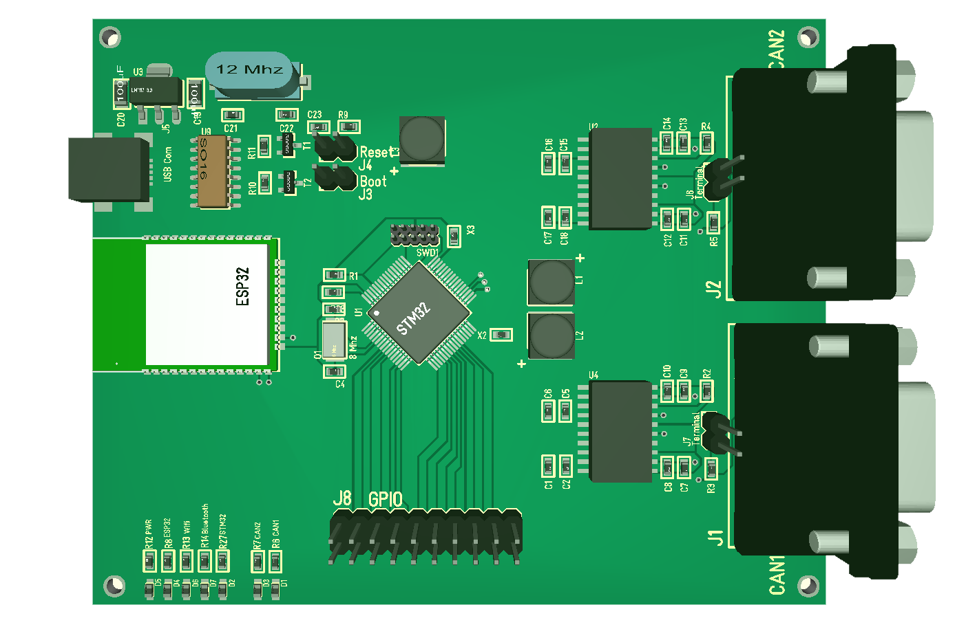
This model is not complete, but it gives an idea. I still lack the battery and the TF Card. The objective here is that I need a low cost CAN Adapter with Wifi to create an adapter that always work as an Analyzer as well.
This model is not complete, but it gives an idea. I still lack the battery and the TF Card. The objective here is that I need a low cost CAN Adapter with Wifi to create an adapter that always work as an Analyzer as well.
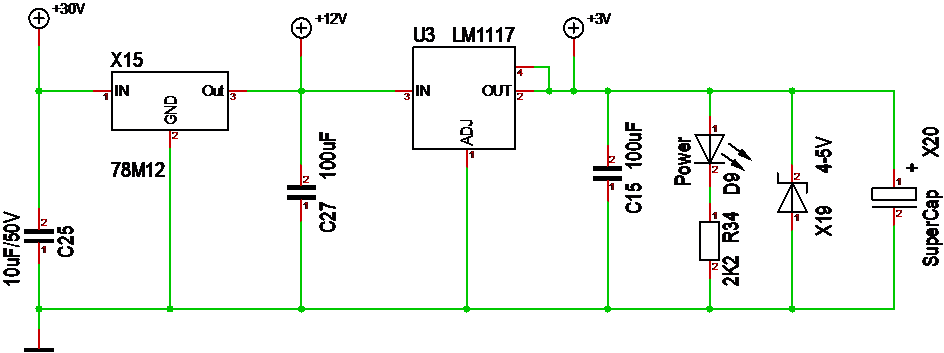
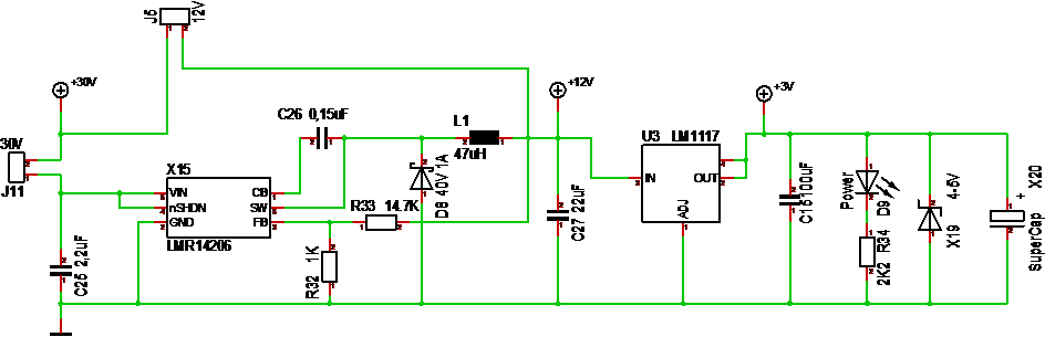
These are the two different PSU’s used on MC4X15A – notice the supercap X20. I mounted a 0.33F Supercap for the purpose of keeping the MCU alive during powercut’s + act as a spike absorber on 3.3V. I am impressed – the PWM cut instantly, but Led’s and MCU keeps going for several seconds.
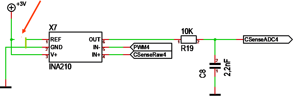
The first thing I noted was that my current readings went into negative voltage, so a bit research and I moved the ref pin 1 to ground – it seems to work better. I won’t know for sure before I activate the ADC and print readings. INA210 is supposed to have gain 200, but I fail to measure that with a multimeter. Lets see what the ADC says.
One thing I do see is noise – lots of it.
These two scope pictures stunned me before I realized the mistake that stunned me even more. The first picture show HEXFET Output in yellow, Logic High/Low Cyan and Purple and BEMF voltage in Blue. The upper picture is with no load and the 2nd is with a DC motor as load. Why do my High signal get disturbed ? Read on and get amused!


The answer baffled me. At first I was puzled by how weak the motor felt, but it was working and the controller with motor used 21mA – up to 40 if I held it. But, what was wrong? Looking at my test set-up I suddenly realized I was driving the motor directly from the STM32 High pin.
STM32 delivers up to 40mA per pin and this motor worked on 3.3V 21mA or something. Connecting it correctly it felt like a formula 1 in comparison.
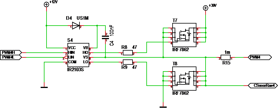
This schematics show the PWM driver stage of MC4X15A. IRF7862 is rated at 17-21A continuous current and pulses as high as 170A, but yesterday I took out two simply because I replaced IR2103 with IR2101 and did not realize that the later have no short-cut protection – so the MCU switched on both High and Low, dragging the PSU down. It was only ca 4A, but with no heat-sinks the SO8 packages will be exposed, so they snapped from overheating.
I planned on burning this board a bit, but not yet – I want to test if it works before I stress test it – lol. Well, new HEXFET’s – new try + I need to remove that IR2101S and get a IR2103S on.
Good news was that I could connect to 3.3V and things worked – it was only the HEXFET part that failed – no marks on the PCB or other Components.
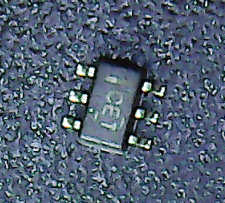
I wanted to share this picture of a INA210 through a microscope. The size of this component is ca the same as a 0603 Component with 6 pins. It is small, but soldering it is not the issue – this bugger have 6 pins and where is PIN 1? I assume it is top left on the current picture, but smallest component I ever have soldered and unclear tagging – yeah – how fun.
I was a bit worried about soldering these for hand, but that seems to be ok with a hot air nozle as long as I can see between the legs and avoid short-cuts. This is a SC70 package it is 2/3 of SC23, and to be honest a 6-pin SC70 – the diodes did not feel so bad as they had 5 pins, but this was a struggle. I think I should consider an alternative solution, but lets see how well this Works first.
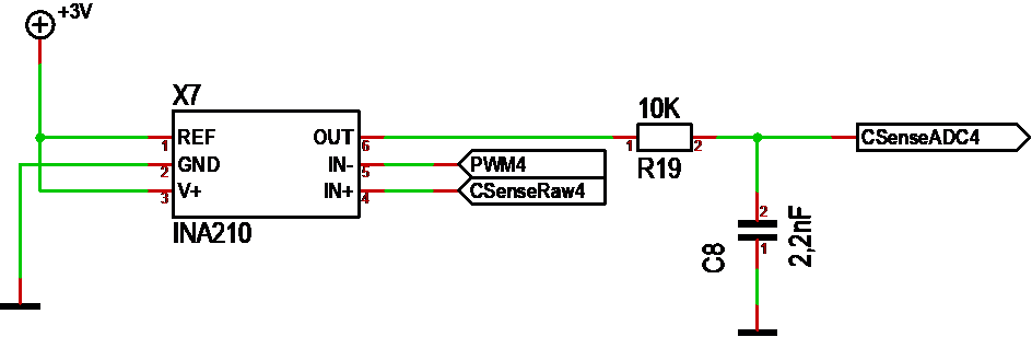
My main concern about the 3.3V PSU ripple is this schematics. It is the current sensor of my MC4X15A Motor Controller. As 3.3V is used as reference and ripple I might see sensor variations I don’t want – basically adding to the sensor noise.

This scope pic is from the 3.3V on my MC4X15A – Universal Motor Controller. The MCU is running and I have the 0.33F Supercap mounted. Ca 200mV point to point ripple is to much for my taste, but it works and this is far better than I have measured out of the Lab PSU’s. I am also using the DPS5005 in this case just to see if it worked at all.
This started as a small experiment as I wanted to see the effect of swapping out the inductor on my LMR14206 – I obviously need to revisit my lab PSU design. The lab PSU and scope is located next to each other on the shelf and I only need to switch it on to introduce noise – I don’t even need anything connected. I obviously have introduced a noise source in my lab that I need to figure out.
This is a set-back because I have been extremely happy with DPS5005 before this.
Returning to LMR14206 I seem to be stuck with 200mV point to point ripple. I am also puzled to as why I see the same ripple on 12V and 3.3V, but I will get some help investigating that. The actual reading on the scope pic is much higher, but that is the external noise. The ripple signature will differ a bit from using DPS5005 versus Thaoxin as they introduce different noise pictures. The small spikes you see above is the 1.25Mhz switching frequency of LMR14206 – and just for the record – it’s no problem adding a filter on the 12V and remove this ripple, but that add PCB size and complexity – part of the objective here was small space.
I decided to test my LMR14206 based DC/DC again and replaced the 15uH inductor with a 47uH inductor on the 12V design. The scope pictures was a shock:

This first scope picture show what I saw as 12V out. It is 12.2V, but look at that ripple picture of several voltages. To compare I scoped what I got out of my PSU and what a shock – I saw the same signature in and huge spikes & ripples out of the DPS5005 based PSU.

This is with no load and it show the same noise signature. The Scope above have different time scaling. Replacing the DPS5005 with the older Thaoxin I also instantly saw a different ripple signal from LMR14206 as can be seen below:

This is a bit better as we have 12.2V and +/-100mV ripple out. But, I need to go back and open my DPS5005 to figure out where the ripple noise is introduced.
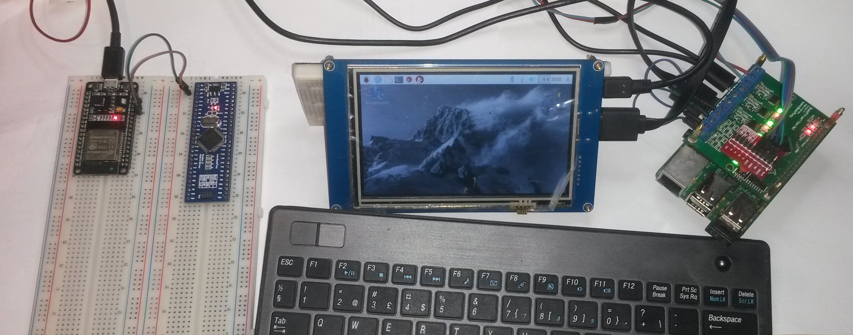
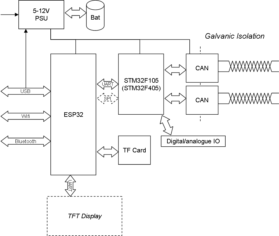
Starting at left is a ESP32 Breakout board, then one of my own STM32F405RG breakout boards, a 5″ HDMI, Wireless keyboard and Raspberry PI 3 with my 5 port Hat – and your right it’s a different Hat with screw terminals, so I do have 2 x 5 port Hat’s working.
What I will do here is to wire up SPI between ESP32 & STM32 for testing, and I can add CAN breakout boards etc getting the boards to communicate. The only drawback here is that I can only use one SWD at the time, but I will get around that.