Galvanic RS485/CAN

Since we talk about galvanic RS485 & CAN Adapter’s I guess it is time to visit this project as well. The universal adapter below was something I started last time I needed CAN. This adds W5500 and ESP12-E + NRF in addition to CAN & RS485.

I never made a revision of this Board, but it served a purpose to test CH340G, STM32F405RG and ADM2582E together. The Board above with the added coil was after my struggle to get STM32 ticking at 168Mhz.

I never tested ADM3053, so that is what I will do next. I see no point sending for a new PCB including parts of this design before I have completed this test.

As for the adapter above – this has in many ways been a big success because I have corrected and re-used a lot of the design I did here, but I will not finish this adapter as such. ESP32 is so much better than the ESP12 or ESP8266 based options. I do however have things left to test on this Board.

Why not Raspberry PI as CAN Adapter?

This is the rev 1.2 of my 5 port Hat with 3 x RS485 and 2 x CAN. I never ordered this PCB because it is only mechanical changes from Rev 1.1. But, using this or a galvanic version with Raspberry PI is an option for my CAN Adaptor plans.

The advantages with this is that Raspberry PI have an excellent HMI option. It would also enable a PLC style adapter where you add on what you need – but it would be a much larger solution as well.

The size difference from a packed, single board solution is not dramatic and it offer other options as you get a proper display, keyboard and a full Linix computer to back it up.

Not so mini CAN Adapter

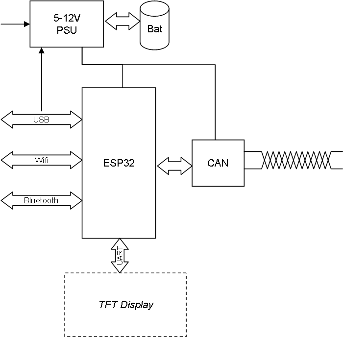
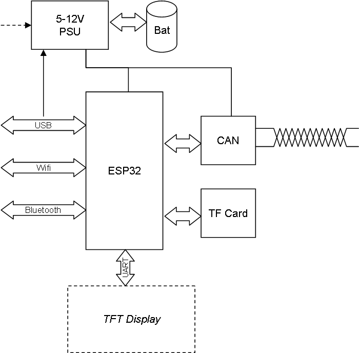
This is the same drawing as the previous post, but I added the TF Card option. Basically this is a small mini-computer Complete With display, keyboard (in the display), Wifi, Storage etc. Just for the record it actually got more “disk” and RAM than my first IBM Compatible PC.

I have never done a TF-card Interface, but I have some breakout boards laying around. As mention you can actually buy this on the NET known as “CAN32” for ca 39.-USD. It comes as a specialized breakout Board for ESP32. But, the good things is that I can easily assemble this on a vero Board to get started – and since someone else have made firmware for this we can use their project and modify it as a starting point.

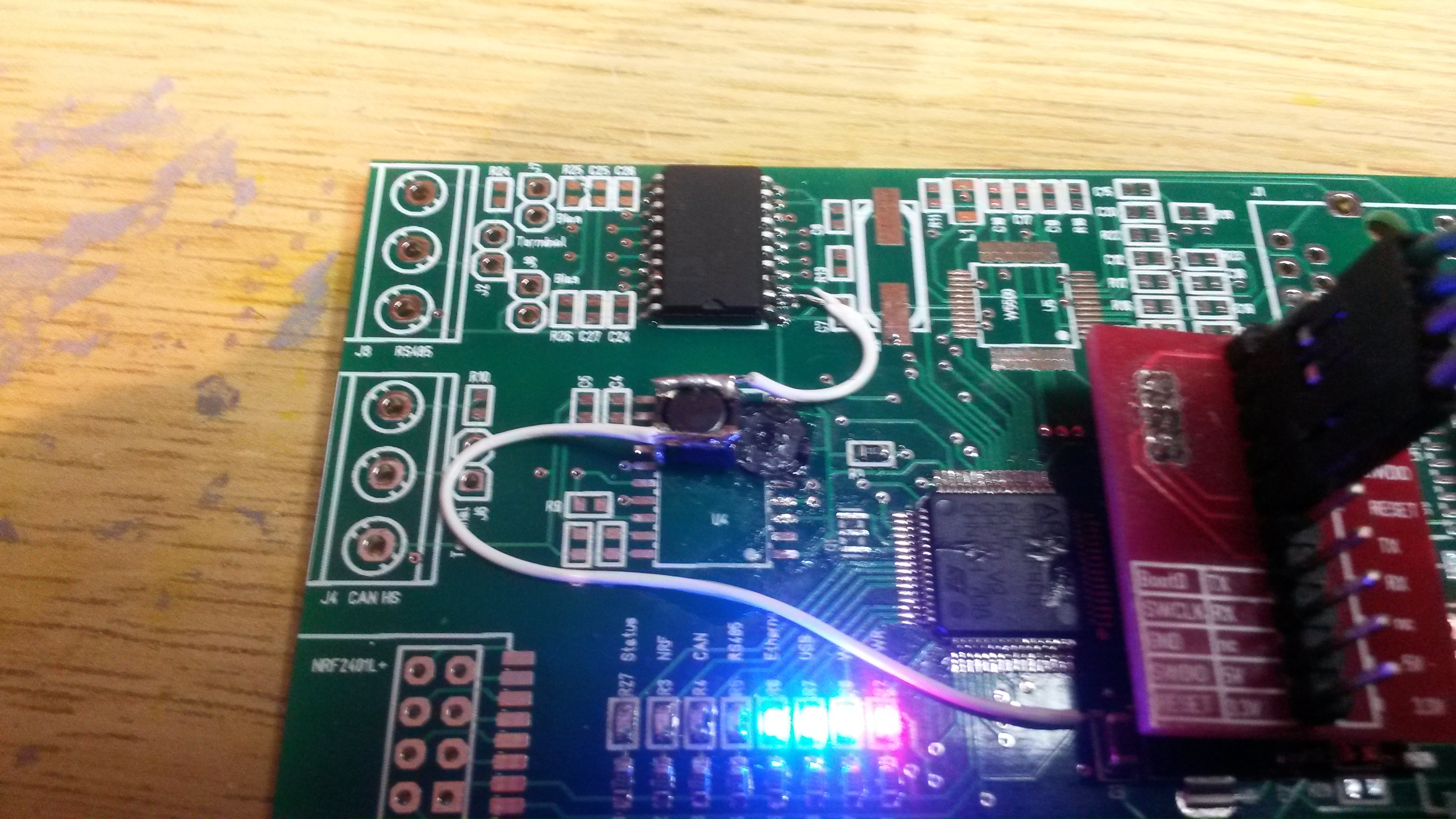
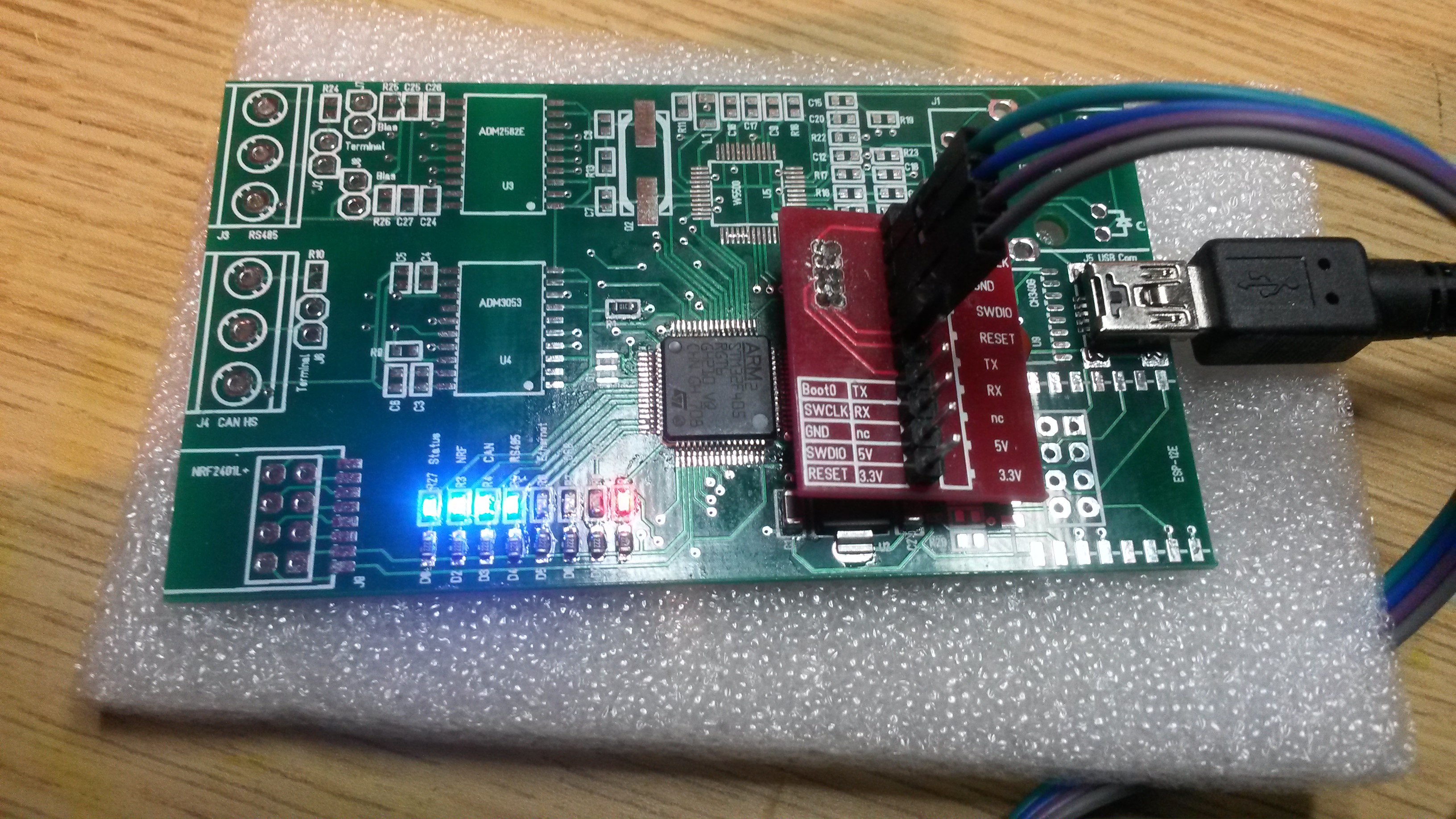
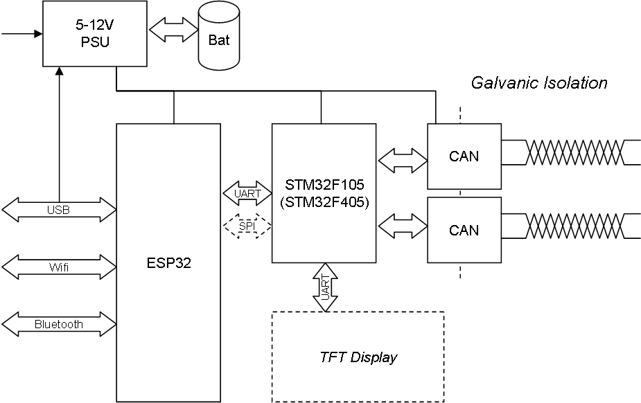
What I want to achieve here is a CAN Tesrter, Analyzer & Adapter – all in one. I need CAN connectivity and I need to see what happens on several CAN Networks simultaneously. As mentioned earlier I will use a STM32 to deal with CAN and make this galvanically isolated later, but this is something I can wire up and start with while waiting for PCB’s.

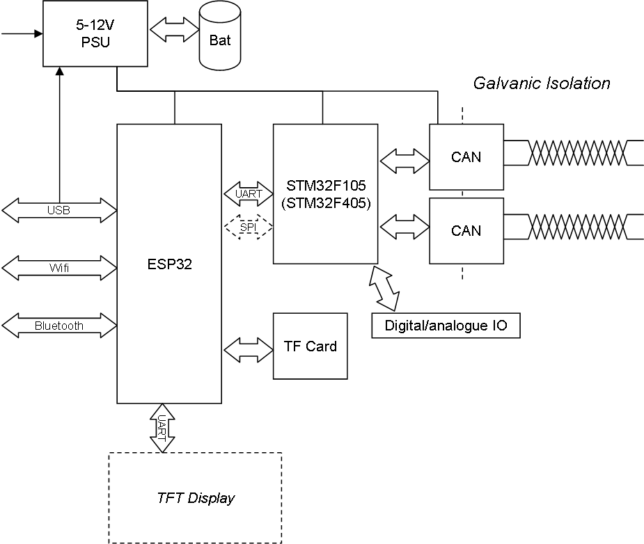
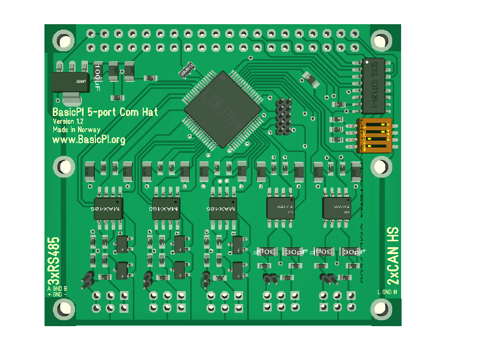
Assuming the TF Board Works out I should also add this to the larger Board. I also think I want to Mount the display on ESP32 and if I have Space add the 16 analogue IO lines from STM32 as a separate port.

This design start to make a bit sence because we now use ESP32 for Wifi, HMI, Storage, while we leave CAN and IO to STM32.

The last part of this project is boxing it. In fact, we could use Bluetooth to connect to our phones/tablets as HMI rather than adding a UART based HMI as well. With Wifi I can obviously connect my laptop as HMI, but the reason I explore other options is because my laptop usually is occupied otherwise and I need the extra screen. Fiddling around swapping screens and turning Smart Phones orTablets on/off is not always the most convenient choice, so having a physical display on the adapter is a priority IMO.

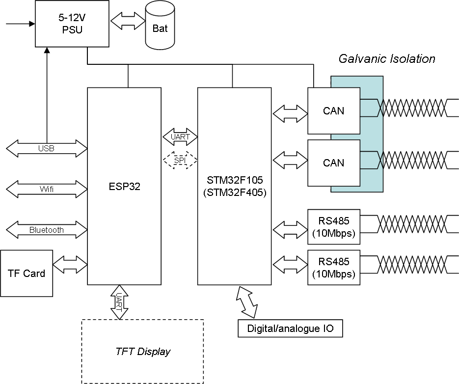
It’s only one flaw here – I am making all this for CAN while I myself am a heavy user of RS485/RS-X. The STM32 I use here have 5(6) UART’s, and if I commit on using STM32F405RG I have 2 x 10Mbps RS485 capable ports that will be very handy for sniffing on my PLC system later. The only thing is that I can’t use galvanic isolation at that speed, but I can live with that.  Woops – wrong! Checking the datasheet of ADM2582E it supports data rate to 16Mbps!

Puh – I better stop writing before I add more into this – my only concern here is what speed I can get between ESP32 and STM32 on UART or SPI. I am hoping on 40ich Mbps on SPI, but that is yet a unknown that I need to investigate. I think ESP32 is capable of this, but it’s more if I am capable of using it – lets see.

CAN32/CANMini

It exist a project that simply add a CAN Tranceiver to a special ESP32 dev Board – called CAN32. This uses the CAN on ESP32 and provide a Wifi based CAN Interface. I have a few CAN breakout Boards and Nextion displays so I want to assemble one of these. The main drawbacks With this is (1) I am unsure about the quality of CAN on ESP32, and (2) it don’t uses a galvanic isolation.

Galvanic isolation complicate things a bit. You don’t really need it for Wifi usage, but you seriously should have it if you connect the USB to your PC With industrial equipment on the other side.

CAN Adapter with Wifi

I need a CAN adapter for a special job and decided to build my own. I use ESP32 to get Wifi, Bluetooth and USB Connectivity, but I decided on adding a STM32 to get dual CAN Connectivity. ESP32 do have an undocumented CAN port as well, but I assume ExpressIF have their reasons for hiding it. The display is because I also want to use this as an Analyzer sniffing. And as a adapter of this type will be connecting to industrial equipment I also want the galvanic issolation.

This will cost me around 20.- USD in components + display and boxing, but to buy something like this I would probably have to pay 500.- to 1000.- USD if I could find one.

I have listed both UART and SPI for communication between ESP32 and STM32 because I am unsure about both on ESP32. I know they exist, but have no experience with them so I can as well just Connect both . I also added a battery option on the PSU.

New DRV8313 BLDC Controller

My previous DRV8313 design used the larger 64 pin F105/F405 MCU and a more complicated sensor design. What I could do is to use the smaller F303 that is 48 pin and fokus on hall sensor driven motors to get size down. The issue is that current sensing is very difficult/unreliable for small motors on low speeds, so ignoring these sensors will simplify the design – reduce size.  The challenge here is that I am not very good at compromizing – I don’t want this BLDC for a project, I want it because I want to experiment with the design and coding – so I want “everything” on it like a spoiled child …

This last draft is the same as before, but I replace F405/F105 with F303 so I can take advantage of it’s programmable Op-Amps to scale current sensing to the motor. I am considering a version where I cut DC Rail, current Sensors and BEMF Sensors as well, but for now I can just design them in and avoid assembling them.

The issue with current sensors is that it’s a huge difference between 2.5A and 50mA. If you dimension the sensor for 2.5A and 500mV you will typically read 10mV on 50mA. The signal get so weak that it risk drowing in noise. So to compensate for this I need to add filters and amplifiers. This also makes it more challenging to control motors on low speeds, while current sensing is excellent on high speeds where you get strong current signals. STM32F303 can compensate for this by using 3  programmable, built in op-amps that amplify the signal. To be honest it is actually far more complicated to make a small BLDC Controller than making a large one.

While I like the STM32F030F4 due to their size they make no sence in this case. I need a 48pin package so I get all 3-phase motor pins and I need the programmable op-amp build into STM32F303.

BLDC Mini Controllers

As I wrote earlier my mini BLDC Controller who support 28V and 2A is basically to powerfully for the job. The motor I Control uses ca 250mA on 12V etc. I used DRV10983 for the job, but I also designed a far more advanced BLDC Controller with DRV8313 earlier. That ended up “larger” as it was 50 x 22 millimeters. But, it also contained current sensors, BEMF sensors. hall sensors With leds and STM32F105.

DRV8313 support 60V/2A, so it’s no wimp and it is basically 3 x Half Bridge drivers allowing you to drive the motors with Your own Logic – FOC etc. This draft have CAN for a change.

The reason I abandoned this was because of DRV10983 that allowed me to downsize, but I also realized that I needed changes on this. I would like to test DRV8313 and I bought a bunch of them, so I will see if I can find time to re-design this one.

2P Motor with Encoder


This is a classic N20 DC motor With gearbox and a Encoder. I made a micro stand-alone Control system for these, but I did not support the Encoder. The Encoder will send pulses back as the motor run indicating speed and relative position allowing us to use this as a small stepper motor.

My micro DC motor Controller was a bit booring – it just worked 🙂 – in this case I want to replace the screw terminal and add support for the Encoder. I have plenty spare pins.  The only difficult issue here is the size. But, I think I will dig in on 50 x 15 millimeters With mounting holes so I get all components on one side.

I also need to re-visit my mini PWM generator and Sensor for the same reasons – Connectors and mounting holes. I admit I focused a bit too much on size alone then I made these.

Another Component is to make a ESP32 With battery capable of switching on/off these as well as operating them – I need to think about that a bit because I could also just use the ESP32 and add the size needed replacing the STM32F030.

Mini BLDC Controller Working

Had a heck of a job getting this to working – seems like I was doomed to do all possible mistakes. First the SWD Connector on the pic is connected wrong, after that the cable was swapped around and finally I banged the wrong pins. To even make it worse I did not manage to get MCU pins working with the CubeMX, so reverted to CoIDE and old libs and voila…

At the moment I am controlling speed through PWM duty cycle and it Works “ok”. 3.3V is also working well giving me 8-28V range on the motor. The MCU is just ticking on 8Mhz using the internal clock. The next will be to control the motor through I2C, in which case I also get to optimize with motor parameters.


BLDC Mini Controller

This is rev 1.0 of the mini Controller. I patched the 3.3V on the back-side so this is feeded 3.3V from DRV10983 and Works fine between 8-28V IN. I also added 1000uF capacitors that I hope will be sufficient to absorb sparks. I have not added the MAX3485 yet, but I can test without this.

This shows the Controller + motor Connected. The vero Board in the midle is so I can measure phases on a Scope. Time to Write some test code.

Reading the datasheet I should be able to Control the DRV10983 simply by sending a pulse between 1KHz to 25KHz. The duty cycle is the speed. But, I also have I2C Connected for the more Advanced Interface.