CAN/RS485-Wifi Adapter

I have mentioned that I need a dual CAN to Wifi Adapter as well as a dual RS485 to Wifi adapter, so I decided to make one that can serve both needs. This uses ESP32 to get Wifi, USB and Bluetooth and a STM32F405RG to get dual CAN as well as dual 10Mbps RS485 – all galvanic isolated.

The CAN Adapter is for professional usage, while the RS485 is partly as an adapter to my PLC system as well as a Wifi adapter to my DPS5005 & DPS5020 based PSU’s.

Layout on this was a bit tricky due to the size of the 9-pin D-Sub connectors and I am not done, but the current draft look very promising. Hopefully I will have this in rev 1.0 around October. Size is 100 x 70mm.

I actually started end partly developed a different adapter last time I needed CAN. I never finished that design, but much of the design is tested, verified and reused here. The only missing part is wired Ethernet.

ESP32 Oscilloscope & Logic Analyzer

Most of my Oscilloscope & Logic Analyzer needs are on frequencies below 1Mhz, and ESP32 have 16 12-bit ADC channels, so it would not take much to create a 16 channel low frequency Oscilloscope/Logic analyzer. This is why I bought a ESP32-WROVER dev kit. Wrover have 4Mb SRAM as well as all the features of ESP32.

Max sampling rate on ESP32 is 2Msps. The details here are not well documented, but if we assume a minimum of 10 samples per Hz we should be able to sample frequencies up to 200Khz. Even more interesting is that ESP32 contains support of programmable Gain through it’s logic pad’s. Again I must state that my knowledge in this area is limited and so it doc on the subject, so I need to experiment and see what I can achieve.

The good thing is that all I need is a breadboard and a kit costing 10.- USD to test this out. No guarantees, but it will regardless be interesting playing with the ESP32 ADC channels.

INA210 – Current Sensing

These scope pictures are from MC4X15A measured at 0,5A and 0,7A on the PSU. The yellow is just the pulse trigger, the cyan is the actual CSense on ch1. The cyan line is the CSense. CSense seemed to increase in average as I increased voltage. Phase current is larger, so a 200mV signal might be ok-ich – I have not done the math exact – 0.5A is ca 0,1V and looking at the scope average 64mV that is 0,32A while 77mV is 0,39A – the math don’t add up so I am not sure what I am looking at.

Measuring the shunt with a multimeter I get 0,3mV which indicate 0,3A while the PSU indicate 0,5A – Increasing to 0,7A I measure 0,5mV which calculate to 0,5A – so the shunt seems to be “ok” with a 0,2A difference from PSU – but keep in mind that numbers are not exact here and it’s a difference between PSU current and phase current.

I have a filter AFTER INA210 that I will remove + I want to look at a non-amplified signal on CH2 to compare. I also need to sample and compute in SW with an actual ADC – I can only repeat that I am not convinced by INA210 yet. I will add proper load later so we can test higher currents. I did test 0.9A, but the scope pic did not convince me.

DS18B20 – Temperature Sensors

I need to add temperature sensors to my MC4X15A Motor Controller so I can monitor HEXFET temperature and cut the H-Bridges to protect the HEXFET’s. I have 2 analogue input’s designed for temperature sensors, but I also have a bunch of DS18B20 laying around.


DS18B20 is a one-wire protocol device and you use it’s IO port to bit-bang 2-way communication. You can actually program 18B20 with threshold values to give alarms and connect it as a network. It is a very advanced and popular device. It also have internal reference so it gives temperature with +/- 0.5 degrees accuracy.


I have a bunch of these around, so I will connect one through the end-point connector. On the next revision I will modify the these ports to use these. I actually could use the temp port as is and the parasite mode illustrated above as well.

Low Cost Programmable Load

I need a load for testing and fancy a programmable load. My first idea was to use a resistor array and a relay operated switch board as illustrated below.


Next as I looked into more intelligent techniques I also realize how easy it is to make one using a DAC and power transistors. The concept is illustrated below.

I borrowed this illustration from the net, so we can use a MCU with DAC+ADC for the job and add a HMI, transistor array and heat-sinks – should be very doable.

Motor Controller – Current Sensing

I don’t get much sense out from the INA210 at 0 – 2A. Firstly I realize that I use a far to large Shunt resistor. I use a 0.1R by mistake. 100mA would give 10mV that amplified with 200 should be 2V. At this size the Shunt become my weak point. At 3A it starts getting very warm as I dispose 0,9W and it is rated at 1W. I need to replace this, but I accidentally lack smaller shunt’s yet.

With 15A and 0.001R I should get 0,015V that amplified with 200 should be 3V. With a 12 bit ADC giving a range of 4096 I should in theory have a current sensitivity of ca 4mA (15A / 4096).

For now I need to wait on 0,001 shunts, but I will find a load that can support 0-150mA so I can test this range.

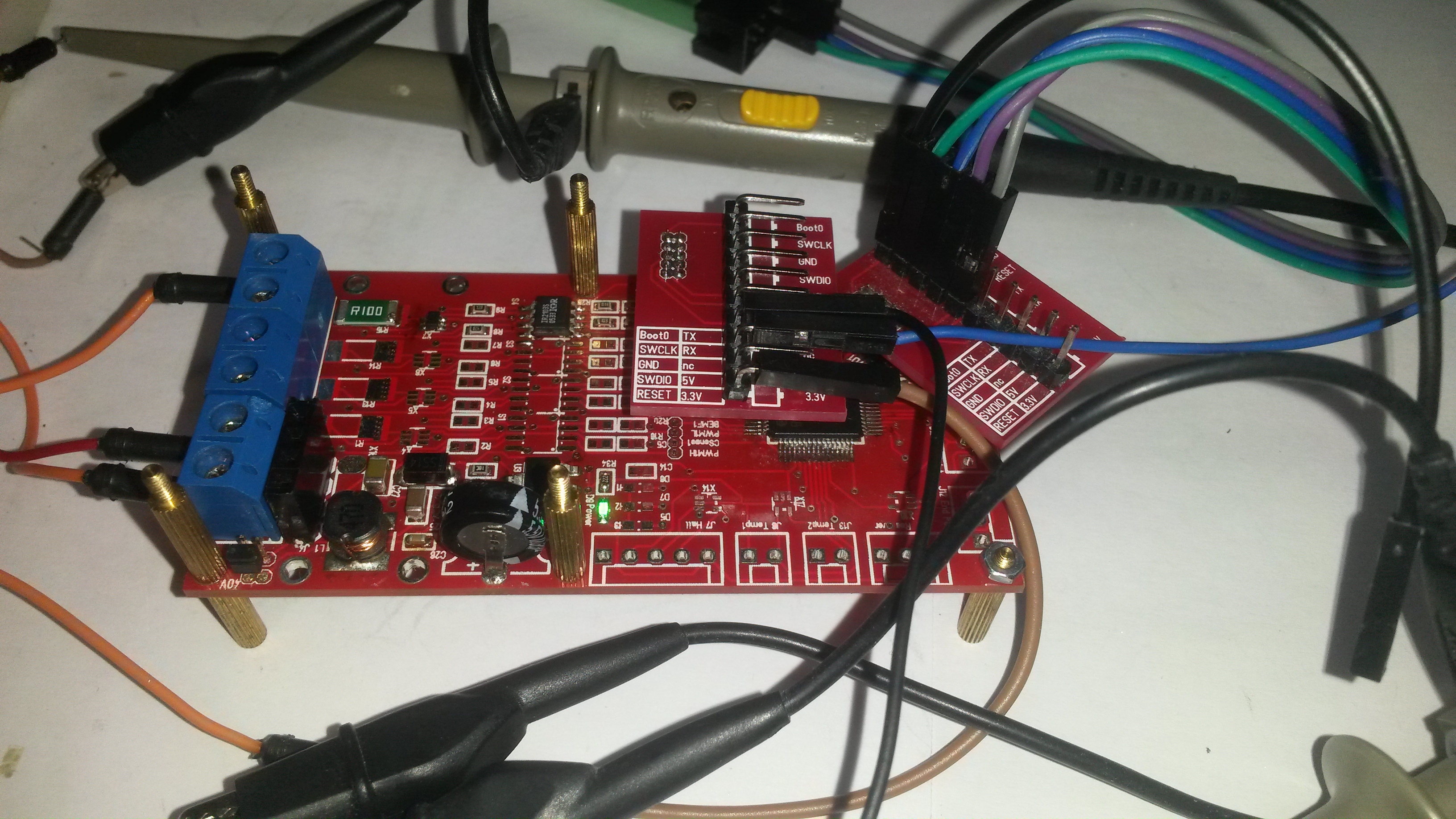
I want to test INA210 a bit more to see if I get any sense out of it, but it cost 50c and the tiny package makes it a pain to use. Using a 2 layer PCB I am also at a disadvantage regarding noise.

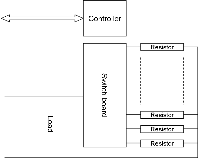
As for load testing… I am melting my load at 3A. I use 10 x 0,47Ohn @5W in series to create a 4,7 Ohm 50W resistor, but it get so hot that it melt the soldering tin on my home made load. I have mounted a 40x40x10mm Heat-Sink and the only component getting hot is my 0,1R Shunt. I can manage 10A out from my Lab PSU and that will have to do for now. But, I want to move load testing to a  different boards with only PWM driver Circuit before I continue. It is basically so much work to solder a full board that I don’t want to destroy this one. Have been replacing 5 x HEXFET’s so far as I tested without heat-sink. I can only sustain 1A without a heat-sink on. I need to do the math here as I expected more.

All in all – this design seems to work. It will be down to current sensing and finding an optimal heat-sink I think. But, I am currently only testing 3A and it’s a way up to 15A continuously yet – mostly stopped due to lack of test equipment as we speak.

Programmable Lab PSU

I fancied testing my MC4X15A motor controller as the driver for a PSU. The code is very simple as I bit-bang a PWM with 50% duty and use filter consisting of a 100uH coil and 1000uF capacitor.

The result was quite good. I did however notice some input ripple. As I also scoped the Lab PSU output I saw a much, much smaller of the same ripple. Replacing the cables the input ripple improved. What happens is that due to wire resistance we get a power drop as we start drawing current. The drop was actually 1V before I changed cable.

My home made little PSU actually worked quite well. I would have needed a better filter, but output ripple was not horrible and if I had put a decent driver and wiring it probably would have disappeared.

I used 100uH, but a real PSU would use something like 10uH to get a lower power drop in the filter. My motor controller hold it’s ground at 1A, but temperature on HEXFET’s started to rise at 1,2A. I need to work on cooling obviously.

MC4X15A – Motor Driver Testing

I am so far happy with the MC4X15A PWM channel with the exception of the current sensor. I have 3 more channels to solder up, so I will do the next without the low pass filter for comparison. I did not like the scope pictures, but will be interesting to see what I can do in software.

This picture illustrate some of the challenges involved in scoping. I am using a 2nd SWD adapter to get hold of the 4 pins so I can scope them while testing. As mentioned while I meade this I intend to destroy a few boards to learn the driver limits. I accidentally burned transistors with a shortcut, so will be interesting to see the limit as I add heatsink.

I am also running the MCU at 8Mhz yet. It will be interesting to see what happens as I increase frequency and things get more sensitive as I have a lot of noise at moment. The HEXFET’s have a 30V limit, so if the PSU noise is an issue I will replace the DC/DC with a 78M12. One thing that works well is the supercap. I am surprised of long it keeps the MCU ticking after power-cut and it should do wonders in absorbing spikes and protecting the 3.3V.

One of the next things I will do is to solder up a PWM channel on a separate board and burn it. This test is a bit tricky as I don’t have a Lab PSU to support the test yet.

3.3V Supercap

These are the two different PSU’s used on MC4X15A – notice the supercap X20. I mounted a 0.33F Supercap for the purpose of keeping the MCU alive during powercut’s + act as a spike absorber on 3.3V. I am impressed – the PWM cut instantly, but Led’s and MCU keeps going for several seconds.