I have 2 different diagram techniques that overlap PLD and UML State Diagrams. In reality I could merge the two to one and then let it up to the user how detailed the diagrams needs to be. A possible hybrid diagram is shown below.
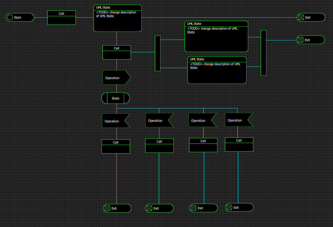
This diagram is obviously a fake, but I just wanted to illustrate the outcome. The fork and join symbols are excellent for visualizing parallell processing. I am not sure I would keep both UML State and PLD Call symbols because they basically do the same things.
UML State Diagrams are typically drawn horizontally while PLD is drawn vertically. PLD is better at visualizing high level logic, while UML State Diagrams are better at visualizing signal flow in a system. As UML State Diagrams have no logic you will sooner or later need to use something else for that purpose anyway. A diagram in PLD can be a sub-diagram in UML State Diagram and vise versa – in fact PLD only lack the Join and Fork components to be able to draw diagrams that look like UML State Diagrams.
Readers new to PLD will probably be a bit alien to how Plain & PLD deals with signals – a function can have multiple entry points and multiple exit points (events). PLD can visualize events in two ways – one as a straight line since every line in this diagram is an event – or by using the event symbol in cases where you want to. The event symbols actually only visualize the events – they are not needed. Which is why you see them at bottom, but not in other parts of the diagram.
It will be a while before I work on this so I will let the idea rest a bit. If I do this then it basically will be up to the user if he want to stick to UML or draw hybrid diagrams. I never liked the terminals on UML State Diagrams, so making these hybrid terminal symbols make sence since PLD terminals lacked a clear, visual difference between start and exit signals. In reality I could keep the UML State Diagram terminals as internal connection points. This one need some thinking – fun for later.
I am not so fuzzed about wherever I am spot on some UML standard or not – this is not a drawing/modelling tool – it is a programming tool. Your one button away from executable code, and the objective is to create large systems faster and with better quality – the diagrams and symbols are only techniques to achieve that – and yes the demo above looks messy…