My previous entry show how to pre-calculate a Sinus table so we avoid doing this full speed because the next step is to convert this into a PWM pulse. A PWM pulse is measured in time – length – so we need to know the max length of a pulse. That is decided by the frequency we use. 4000Hz is really a minimum, thought if you drive a slow motor you can get away with a slower algorithm. This is the frequency of the timer interrupt we will use to re-calculate PWM output, so a pulse of 1 is 1/4000 in length.
The second is that we need to apply torque where “1” will be 100% torque, 0.5 will be 50% torque etc.
The third element is to scale to a length number matching the timer we use. To sum this up I pre-calculate a pwmFactor as follows:
pwmFactor = 1/4000*timerScale*torqueFactor;
I only need to update this if I change torque. This now gives me a factor I can multiply with the vector to calculate the length of the PWM pulse for each phase.
aPWM = vector[x].a * pwmFactor;
bPWM = vector[x].b * pwmFactor;
cPWM = vector[x].c * pwmFactor;
The final step is to output this pulse by switching pins on/off. Assuming I did not have a Hardware timer I might need to create a much faster interrupt that only switched pins on/off, but luckily the motor timers on MCU’s like STM32F405 will do this for us – I will be using Timer 1 that is a specialized motor timer that will do a lot of the work that otherwise would be hard to achieve – hard, not impossible. We run motors using slow AVR’s and PIC’s, but using a modern MCU with a motor timer is just so much easier.
As I am driving blind-folded with no knowledge of my current rotor position I just do exactly the same as in my Trapezoidal example and iterate through the table. The speed I iterate (change sinus entry) is now the motor speed. Assuming you use 4000 Hertz and have a motor with only 3 coils you can routhly acieve 10 rotations per sec without skipping vector entryies. This is ca 600 RPM, so if you use a faster motor you really should increase freuency, but increased frequency means more CPU used for math and more loss in the MOSFET’s. You also have an upper limit of what driver, MOSFET and motor will support. A common range is 4000 to 20,000 Hertz.
At this point I don’t know the current rotor position so I just use the vector table knowing that as I iterate the motor will be moving most efficient on a 90 degree vector as illustrated below:
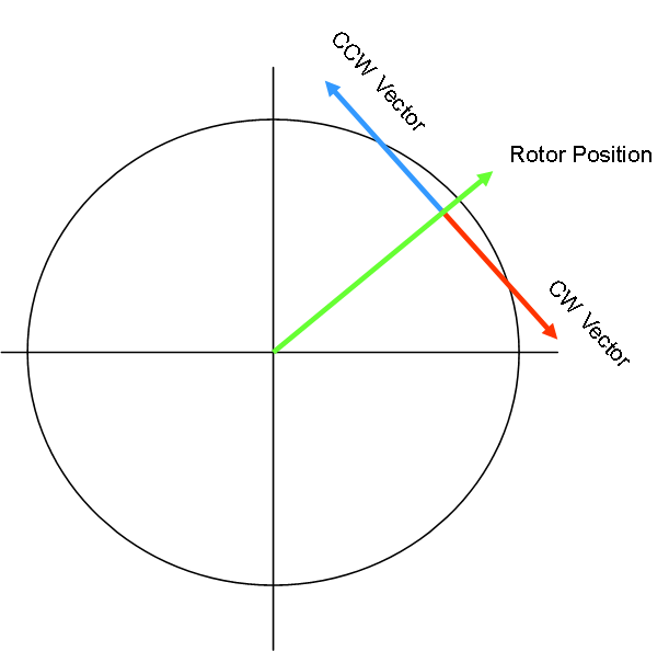
If I had known the current rotor position I would have looked up the vector table 90 degrees before or after the current rotor position. But, to do so I need to use BEMF, Hall or current sensors to calculate my position. In theory we could calculate this every time we create a PWM output, but we face two challenges (1) CPU hungry math and (2) inaccurate input.
Phase currents can in theory be measured calculated for every PWM output, but you usually have so much noise that you end up filtering – meaning you will not have ADC measured currents as often as you output PWM. Hall have a lower accuracy. So the real algorithm usually use a trick where we use sensors to correct rotor position.
By adding rotor vector calculations I basically are doing FOC (Field Oriented Control). I will be using both Current- and Hall sensors. My cutter motor have no Hall and it will be driving fast so this is excellent for current sensors. The wheel drivers do however have Hall sensors and will be driving slow – I do not expect any valid input from current sensors on the wheels, but we will see – so I will be driving based on Hall only.
One advice – before starting putting on PWM on a motor you need to activate temperature- and current- damage thresholds. I have four temperature sensors and two of them are located in between MOSFET’s. If the temperature raise fast or we ever achieve a selected threshold we simply cut the motor to avoid that electronics get damaged.
I also need to do this on phase currents – the MOSFET I use have a maximum of 100A, so if we ever reach – lets say 75A – we cut the motor. Maximum pulse is 400A. This is MOSFET specific data and I have used a wide SOP8 with padding underneath – a package used by several MOSFET’s so I can adapt MOSFET to application – I have 60V MOSFET’s, but I am using IRFP5300 since I had a bunch of them – this have a RDS=1.1mOhm, 30V, 100A etc – excellent for my current applications since I will be using 18V batteries from a local DIY shop.
Two numbers on a MOSFET are very important – (1) RDS that needs to be as low as possible and (2) switching time that needs to be as fast (short) as possible. As we switch we move into an area where the MOSFET will consume more heat – a low frequence is good as we switch more seldom, but a low frequency is no good for faster motors – this is a tradeoff you need to make knowing that higher freuencies will increasingly heat up your MOSFETs. For a SOP8 style package I assume max 1W dissipation without heatsink – meaning that if we burn more than 1W on the MOSFET temperature starts to raise fast. This imporves with heatsink that I have on each driver – but we are now into the discussions about my boards limitations – my target was 50A, but at some point I will destroy boards to learn these numbers.
I just tested PWM outputs on my board and is happy to see they work, so I only need to get temperature- and current- sensors working and I will be spinning the larger motors.