I will try to annotate the motor driver algorithms starting with a simple, brute force Trapezoidal algorithm. If you try to read papers on motor drivers you will see a lot of advanced math, but you will find very few papers explaining how simple it actually is, so I will try to do that here.
I borrowed the excellent drawing below that illustrate the 3-phase motors with windiings A,B and C. Actual motors have more windigs. You will find 6, 9, 12 windings and more on actual motors, but the concept is the same. To drive this we need to apply a pulse on A, B and C in sequence.
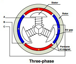
If you look at the windings you will see that A alone can’t drive anything, so to actually have a coil you will need to apply + on A and – on B or C. This leads us to the simplest of the algorithms where you just apply pulses in sequences over and over again.
- A+ B- (C is off)
- A+ C- (B is off)
- B+ C- (A is off)
- B+ A- (C is off)
- C+ A- (B is off)
- C+ B- (A is off)
A simple Trapezoidal will apply the pulse in sufficient length so the motor is garanteed to step one step. But, as you don’t know the current position you might have 5 steps before your motor starts. As we drive blindfolded we increase speed by making the steps faster. To drive the other direction we just reverse the sequence.
Trapezoldal is excellent to drive a motor very slowly and it is easy to code a working example. As we in this example drive without any sensors whatsoever we just have to assume that the motor follow our directions. This can be a bit tricky as we will not detect if the motor stalls and as the sequence goes wrong we just add the the problem. To cope with this we can add sensors.
BEMF basically measure the voltage on the phase we don’t use as this can tell us the actual position.
Phase Current is the current in/out of each coil that can be used to compute the rotor position. The challenge with this is that it needs a bit of speed before the currents become notifyable + it can be very sensitive for noise situations.
Hall sensors are magnetic delectors that will create a sinus as the motor rotates. This can be measured and used to compute rotor position.
Encoders can be put on shafts to accurate measure position.