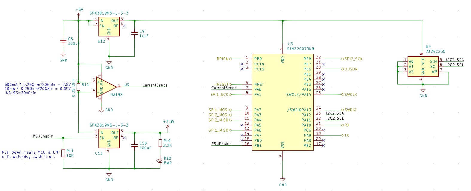
This is the schematics for Device-Bus, current sensor and power switch. I have a stripped down XPortHub that I might use for testing – removing W5500 leaves plenty of space without digging into 2nd side and 4 layer design. I simply would like to make some boards, put them in a stack and test for now.
The challenge with using SPI’s in Half Duplex mode is that I need someone to be Master – to drive the TDM loop. This is a challenge as I start up without anyone assigned this task. I did consider several aproaches and decided on giving Raspberry PI a separate RPION pin it can pull high. RPI starts later than the others, and pulling RPION high will silence the bus – all devices moves to Device mode and wait for RPI to take over. This was the easy one.
The more complicated scheme is if RPI has not started or is not plugged in. At this point we will have several boards fighting over control. So I added a second BUSON pin which tells everyone someone is running the bus. I might use more pins here, but as a device starts it can wait a random time, if no-one switch on BUSON it can do so, wait a random time and if no-one start the clock it can do so. At this point we have used 2 x random number delays – it will take some bad luck for two devices to believe they have the bus, and even more to start the clock at the same time. To be sure we broadcast our uniue ID.
STM33G070 don’t have an unique ID and it don’t have a random number generator, but STM32F405 does so we use that one. The delays I talk about should be 1-100ms, meaning the entire start-up conflict should be settled in max 200ms if we have chaos – at normal start we have flags indicating what roles the devices have.
If we by some strange luck still have two Devices trying to control the bus we will just get garbage as we try to communicate. Each bus have resistors to avoid full short-cuts and we have current sensors that will detect pin short-cuts as well. So all we do is to drop the bus and start over again. Assuming we are master and lose communication we use the same scheme. It also means that if we unplug boards or shut them down someone else will take over the bus – it should work.
Once synched we need to figure out whom is on the bus so we can set up the TDM sequences – this time we have two of them. With two SPI-buses it would be tempting to run two schemes and accept that two different Devices control each their bus. This will however never work with Raspberry PI involved since the Broadcom SPI’s are more limited in the sence they only support SPI Half-Duplex Master.
My remaining challenge now is how do we detect that we are alone on the bus? Lets revert the question – the solution becomes more obvious as we ask for a list of confirmed Node’s we can talk to!
As for the schematics U12 feed 3.3V to U3 and U4 that is the MCU and EEPROM. U9 is an INA193 current sensor. The proposed 0.25 Ohm resistor will at 500mA produce 2.5V to the ADC and at 10mA 50mV to the ADC. I have to test shunt and gain later for a consolidated scheme – I am more interested in currents below 100mA than above, so lets see. I am a bit concerned that low currents will only be noise.
U13 is the power switch. On U12 we bind EN to 5V so that it is always on, but on U13 we connect EN to PA0 on U3 (G070). It has a pull-down so we are unable to switch power on before U3 does the job. This way we switch on G070 that switch on F405 (or not).
U3 is STM32G070KB. Part of the new M0+ series from ST and high spech at low cost. I was considering using a Flash page for data, but decided to add a low cost I2C EEPROM with 32Kb (258Kbit). This can store configuration for F405 as well solving another function I want on all boards. U4 is a TSSOP8 package and the I2C interface is 1Mbits/sec. EEPROM is slower to read/write than FRAM, but I am not sure I care. I can also add a CRC and write two pages etc to avoid havoc if we shut down during writes.
The UART connected on PA10/PA9 is capable of 6Mbits/sec and as we will be crossing TX/RX directly we will be using full duplex. We also have 7 DMA’s so we use 6 on SPI1, SPI2 and UART and still have 1 left for MEM to MEM. We also have 32Kb to use as buffers. I need to use interrups for EEPROM and bit banging for the ADC, but we have sufficient juice as this is a 64Mhz MCU.
Just a footnote that STM32G030KB is half the cost, only have 8Kb SRAM and 2 UARTS, but it’s UARTS are 8Mbps/sec. I2c’s and SPI’s are the same speed. I am having that in mind if we can downscale later. The entire BOM is below 3.- USD. It will take a while to order PCB’s and parts, but I am looking forward to this experiment.
