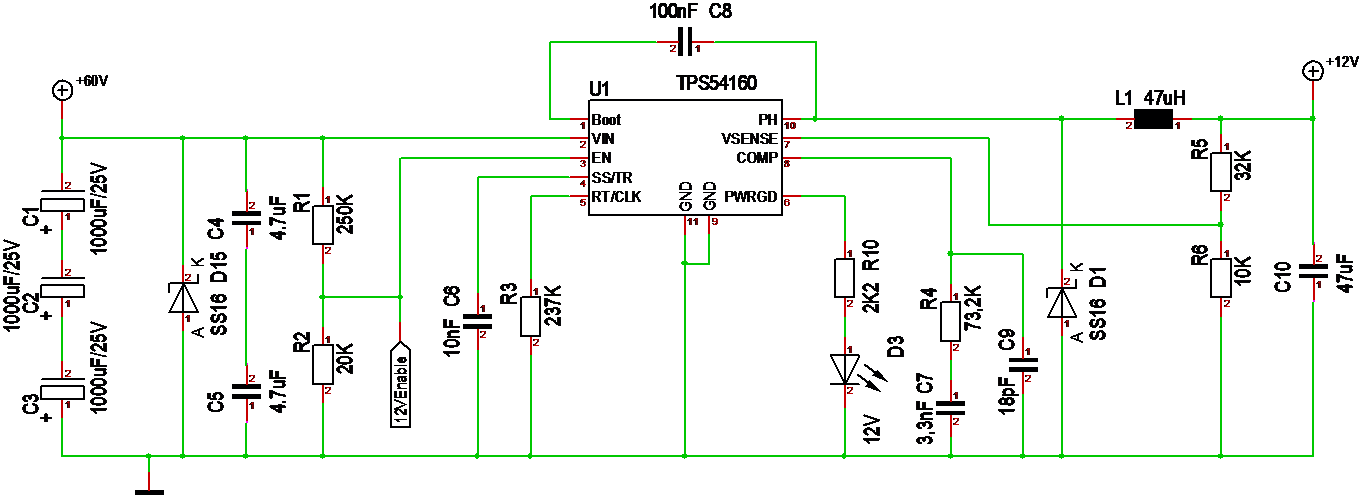
Good news is that TPS54160 is working. C5 & C4 did the trick of getting me past 35V input. I tested 50V In for now. Minor is that the values shown on R1/R2 and R5/R6 are wrong. R1/R2 can be dropped to always enable the DC/DC. R5 needs to be ca 140K for 12V, the value shown is 3.3V.
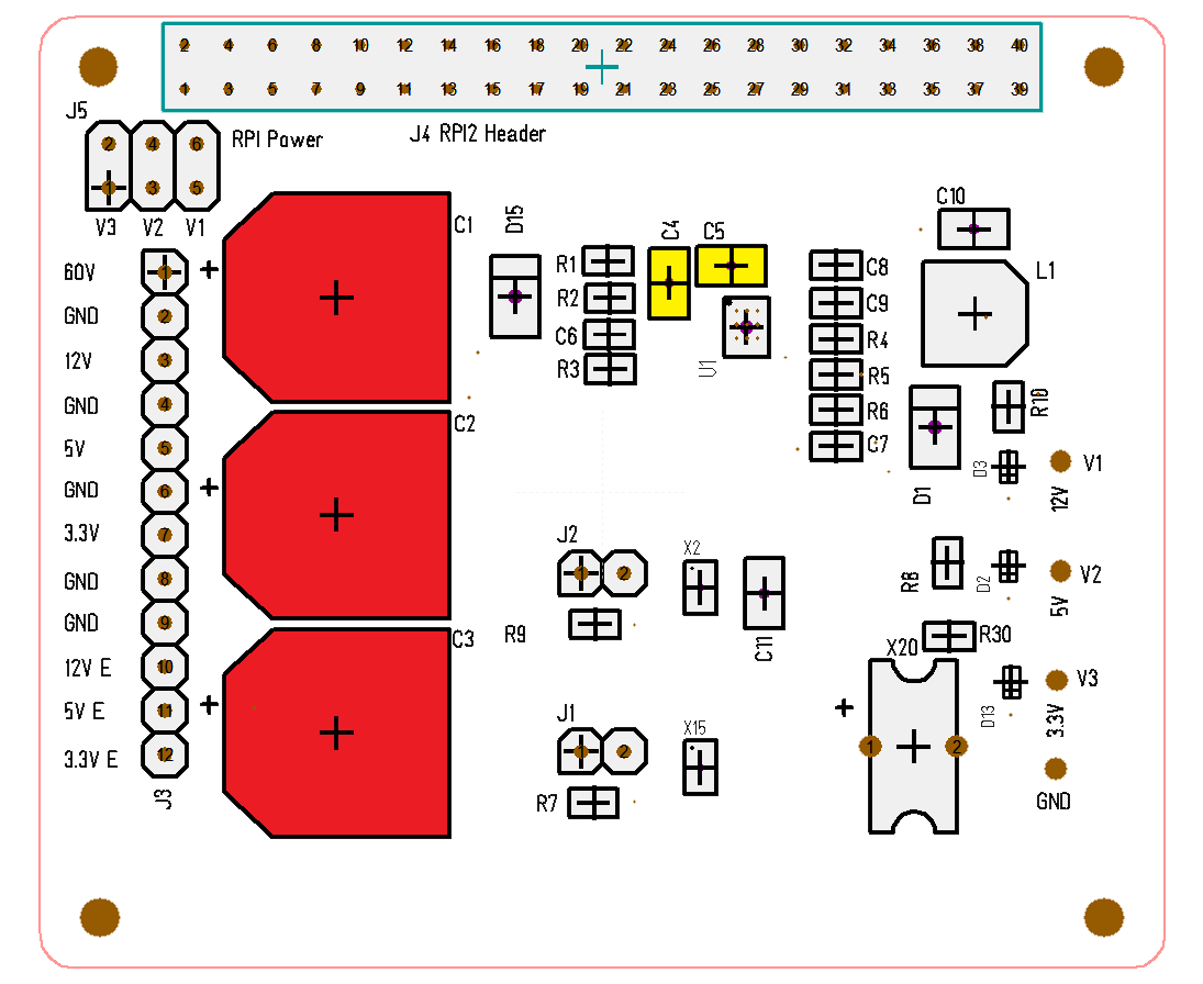
A bit more annoying was the three caps in red. This pic looks like it is sufficient space between them, but it was not. I did not have 4.7uF caps in 1206 size, so I used 10uF (yellow) that worked fine.
I am also a bit concerned about the height of those 1000uF/25V capacitors, so I might need alternatives here. Always good to get a PCB so you can deal with mechanic changes as well. I also wonder if I should add a different connector for 12VE, 5VE and 3.3VE signals to make it easier to connect them to a MCU.
A bit concerning was that the first TPS54160 only gave ca 50% output values. As I changed to a TPS54060 the output value became normal according to datasheet. Datasheet ask for very accurate resistors etc, but I don’t care as long as the output voltage is ca correct.
But, all in all this was a success. I am really happy to see TPS54x60 working as expected.