TPS54x60 is a very nice DC/DC converter covering up to 60V, but the circuit I used on the MC3X60V3A Motor Driver snapped at 30V+. I tested with 2 units before consulting a friend that suggested to add a 10uF capacitor very close to VIN. I have yet to test this because I did not want to sacrifice the one unit I had working. But, I need this 60V DC/DC working because I am using it elsewhere, so I decided to make a separate test PCB to Experiment with..
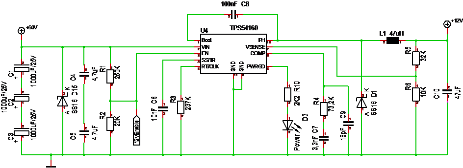
Reading the data-sheet for the TPS54160 I think my fiend might be right, but I am also curious about the EN pin. I left this floating which should be ok, but I need to test this. The last bit is the PWRGD pin which basically should drive a Led or something if power is ok.
Having a special breakout for this makes sense because this is a good circuit for experimenting with values for various voltages. For 24V I can as well do with a simpler linear regulator, but this is excellent for 48V. Yes it says 60V, but as I have explained before using a DC/DC converter at it’s limits with a motor controller involved is asking for trouble.
The next bits I want to add is 5V and 3.3V linear regulators fed from the 12-16V from the DC/DC.
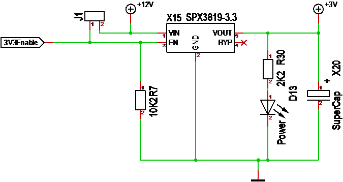
The 3.3V have an enable that can be tied to VIN or driven by an external MCU pin. It also have a 0.33F Super Capacitor. This circuit should deliver 3.3V at 500mA.
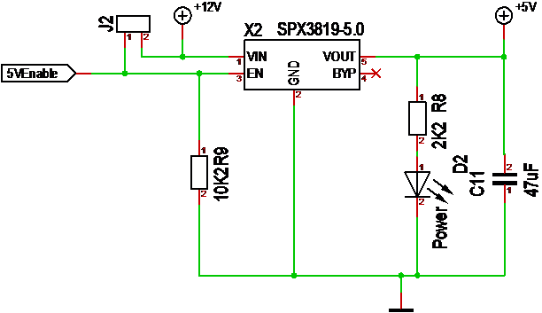
The 5V circuit is identical, but do not use the Super Capacitor. I sometimes need 5V in addition to 12V and 3.3V, and the small SPX3819 deliver 0,5A from a SO23 packet making it an ideal small and low cost alternative.
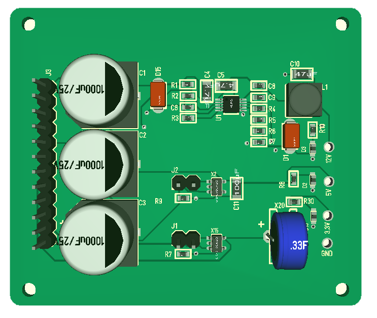
The form factor of this board is a bit big, but the objective is only testing of the DC/DC so that is ok.