I received the MC3X60 Motor controller PCB’s yesterday and as always it is awesome to see how small my designs are. As this is the first time I use TSP54x60 I instantly assembled this to test and was pleased to see 3.4V out.
This circuit worked well giving 3.4V out with input from 12 to 30V, but TPS54060 snaps as I try 35V input.
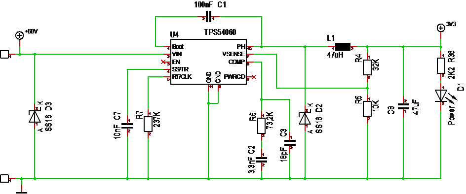
I received MC3X60V yesterday and was very pleased to see the DC/DC actually working. I had to adapt values to E24/E48 series – R7 became 240K, R6 became 75K, R4 became 33K, but it gave 3.4V out which is fine. I can adjust it back with a E48 combination of R4/R5 later, but the requirement is actually 3-3.6V. As I turned up the Lab PSU Input it works perfect up to 30V input, but snaps as I try 35V. Exact same behavior on two different TSP54060 chips so far.
This was a bit disappointing because it should not have snapped before I reach 65V, but I will test with TPS54160 and TPS54260 as well. I will also solder up a 2nd circuit. I also detected that the circuit behaved strange if I did not have a 1000uF capacitor over the 60 attached. I have double checked the circuit and components – it is only the TPS54060 that snaps.
My first thought is that I have gone wrong by leaving pin 3 and pin 6 floating. Pin 6 can be left floating it states, while pin6 is an output signal.
Regardless – I also have TSP54160 and TPS54260 chips to test + I only planned to develop with 12V anyway, so I can continue on two paths here (1) testing 60V PSU and (2) testing the rest of the motor Controller.
Don’t worry, I will get to the bottom of it. But, as usual I am my own enemy and don’t make breakout boards I can test new circuits With easily. It is straight on a dense, small design. I am a bit spoiled as I get things working most of the times 🙁